LKE & Rocket, “Variant 1”
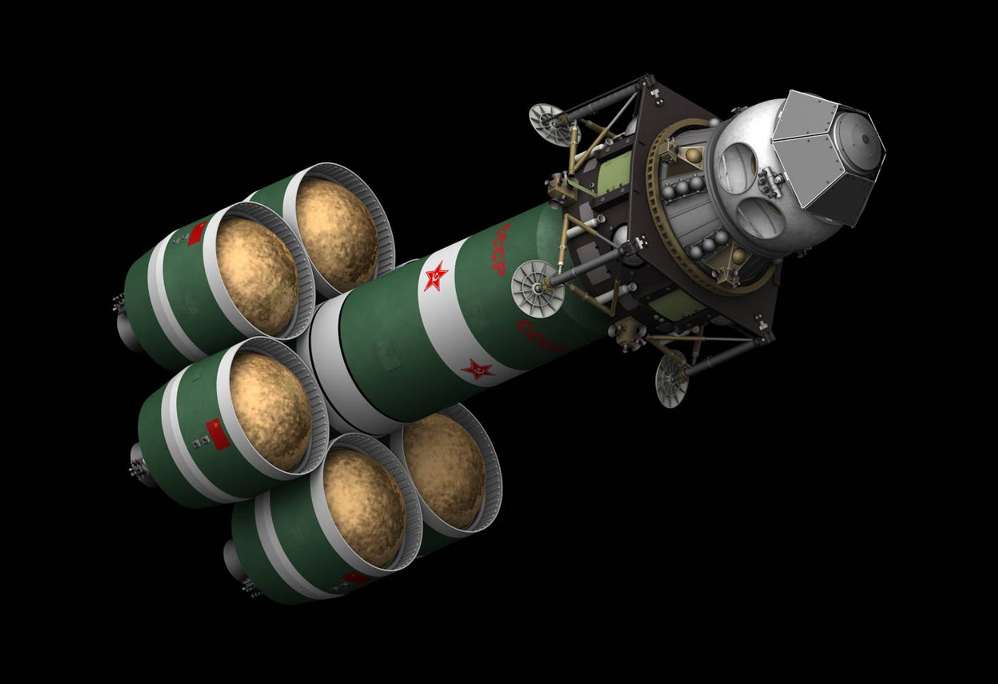
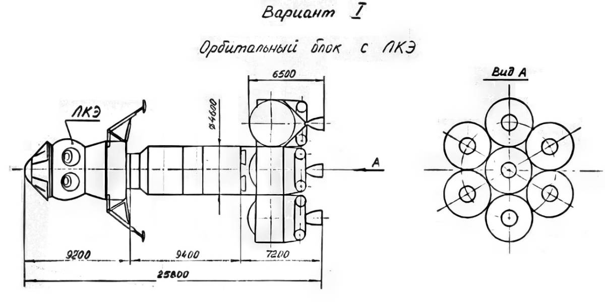
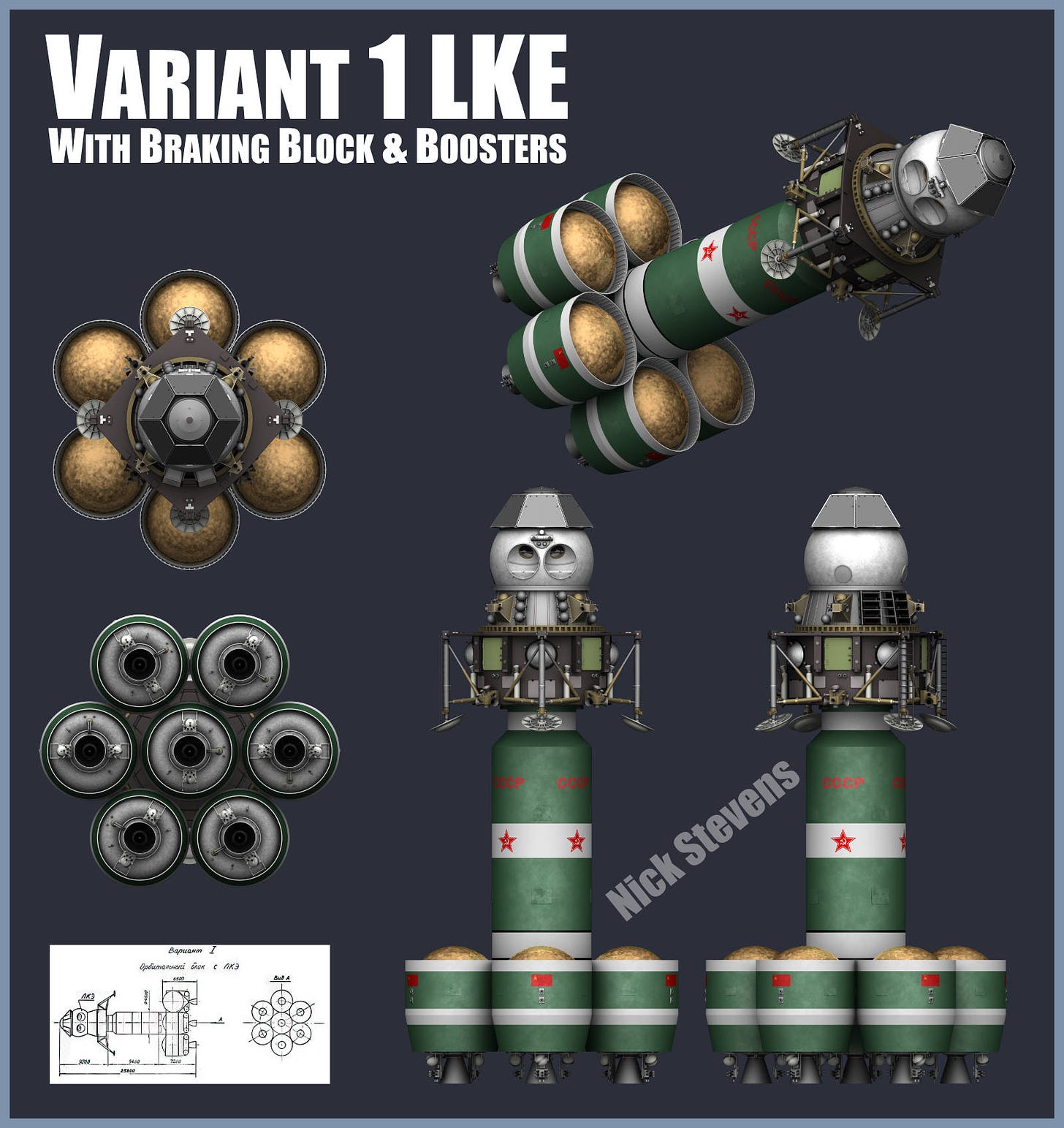
First up, a variation on a craft shown in the pervious post, MTKS Shuttles, a new lunar architecture.
This version is extremely similar, and seems to differ only in that small boosters are attached to the Lunar Craft, rather than simple spherical Hydrogen tanks.
I’ve also made an animation of it, hosted on Vimeo:
There’s plenty more Space Animation on my Vimeo channel, which you can find here:
The Lunar Expeditionary Lander
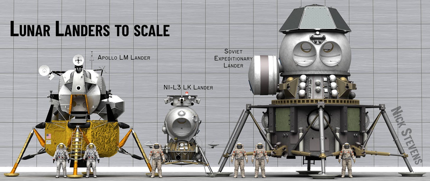
Now it’s not at all obvious just how BIG that LKE lander is - after all, the resemblance to the basic LK is clear. So I made this render, of the LKE alongside the Apollo LM, and the basic LK Lander, so you can see just how huge it is.
The tub on the left side of the LKE is an airlock, diagrams normally show it as smaller, but here it is shown as it is after landing, expanded to provide more room for the cosmonauts.
And here’s a high resolution video, showing it from all angles. Best watched full screen.
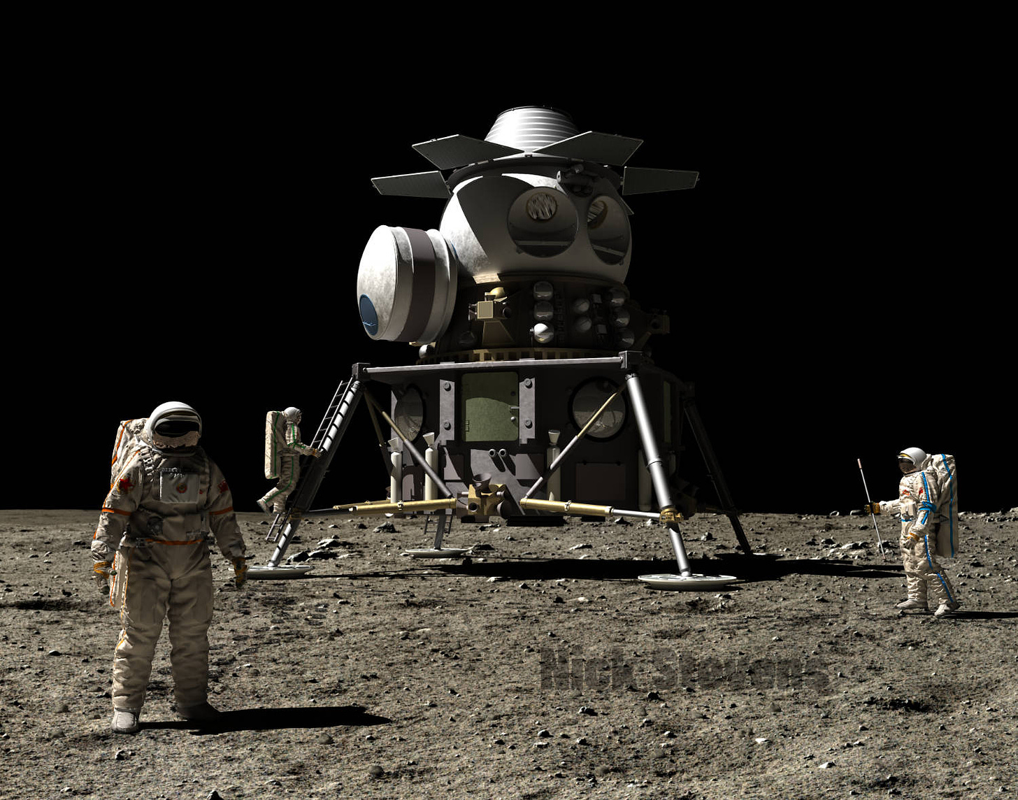
And here’s a render of what it might have looked like after a successful landing on the lunar surface.
On spacecraft scale in general
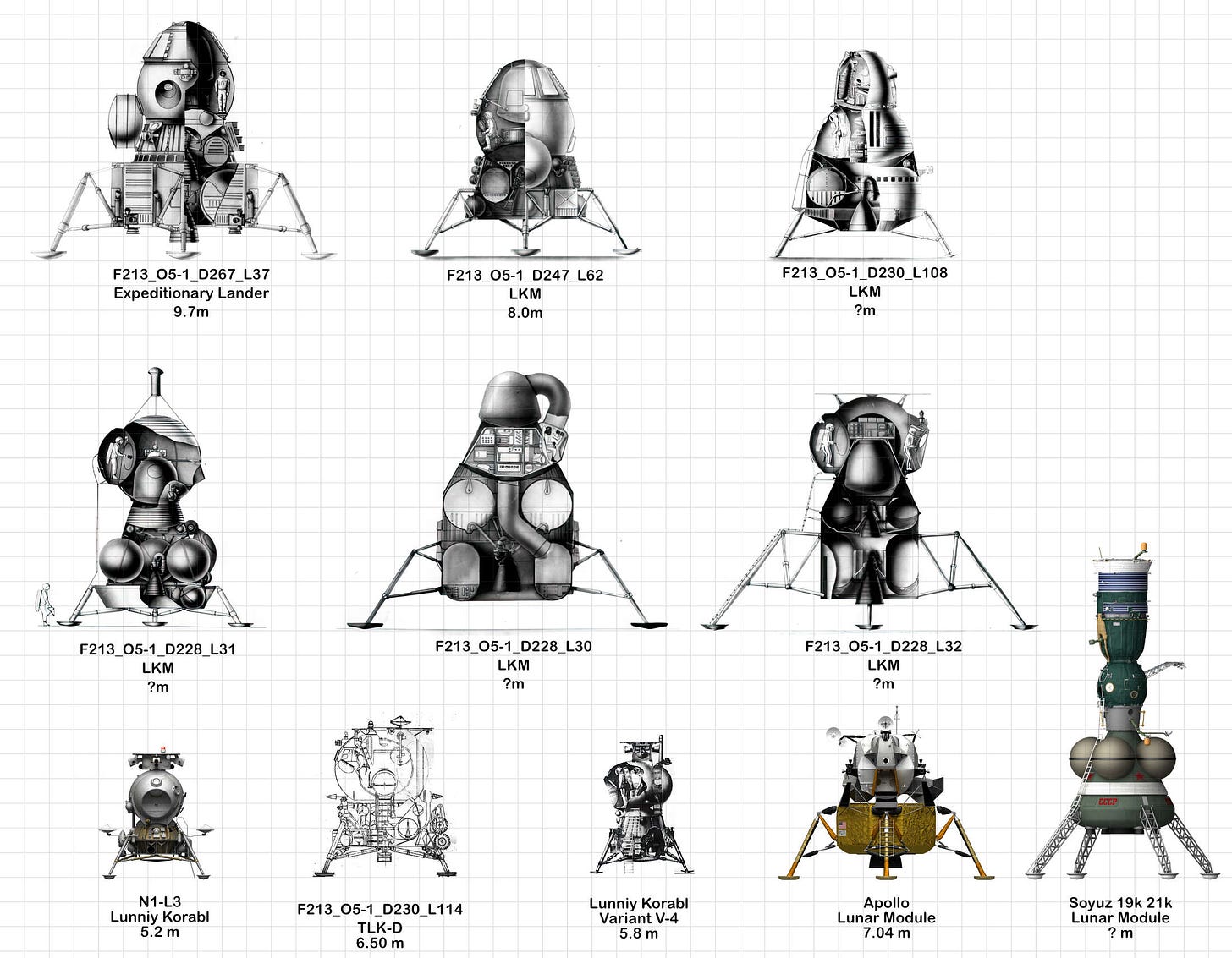
My own misunderstandings of the scale made me think about this more carefully, and I have decided to make an illustration showing all the Soviet landers I know about to the same scale. One of the more obvious challenges with this is that I don’t have an accurate size for many of the designs! So in these cases I am using the apparent size of the cosmonaut as a guide.
Craft with “?m” have an estimated size - the background grid is 1 metre scale, so you can read off estimated height easily enough from that.
This illustration brings out several things REALLY clearly:
The LKM version may look similar, but is nearly 2m shorter!
The later designs were intended to outclass Apollo, and the size shows that.
Even the TLK, (LK Heavy) was a lot bigger than the basic LK.
The 19k-21k remains by far the tallest.
This is a work in progress, and I’m open to suggestions for what info I should include, though I don’t want it to get cluttered. I think adding the date, even if approximate is essential. In case you are wondering the references like “F213_O5-1_D230” are RGANTD references, from the state archive. I definitely need to include the other Lunar Expeditionary Modules, but the illustrations I have are generally 3/4 perspective views looking down. And seem to be changing with new information. One the subject of which…
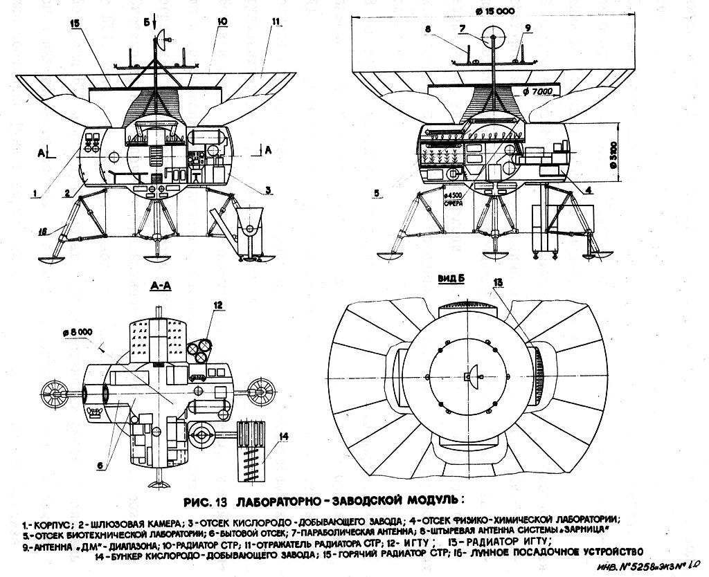
Expeditionary Factory - Err…
I thought I understood this module, not least because it is described in some detail in the RKK Energia Encyclopaedia. Then I see this image:
A 15 metre diameter dish on the roof, around a thermal radiator? It seems to be there to reflect heat away from the thermal radiator. But when the Sun was overhead, it would surely focus light and heat onto the radiator system? At a time losing heat was the hardest? I really don’t understand what is going on here. Could it be only for missions well away from the Lunar equator? Maybe cosmonauts would remove it in the Lunar mornings, and replace it in the evening.
I need more information on what the **** is going on here.
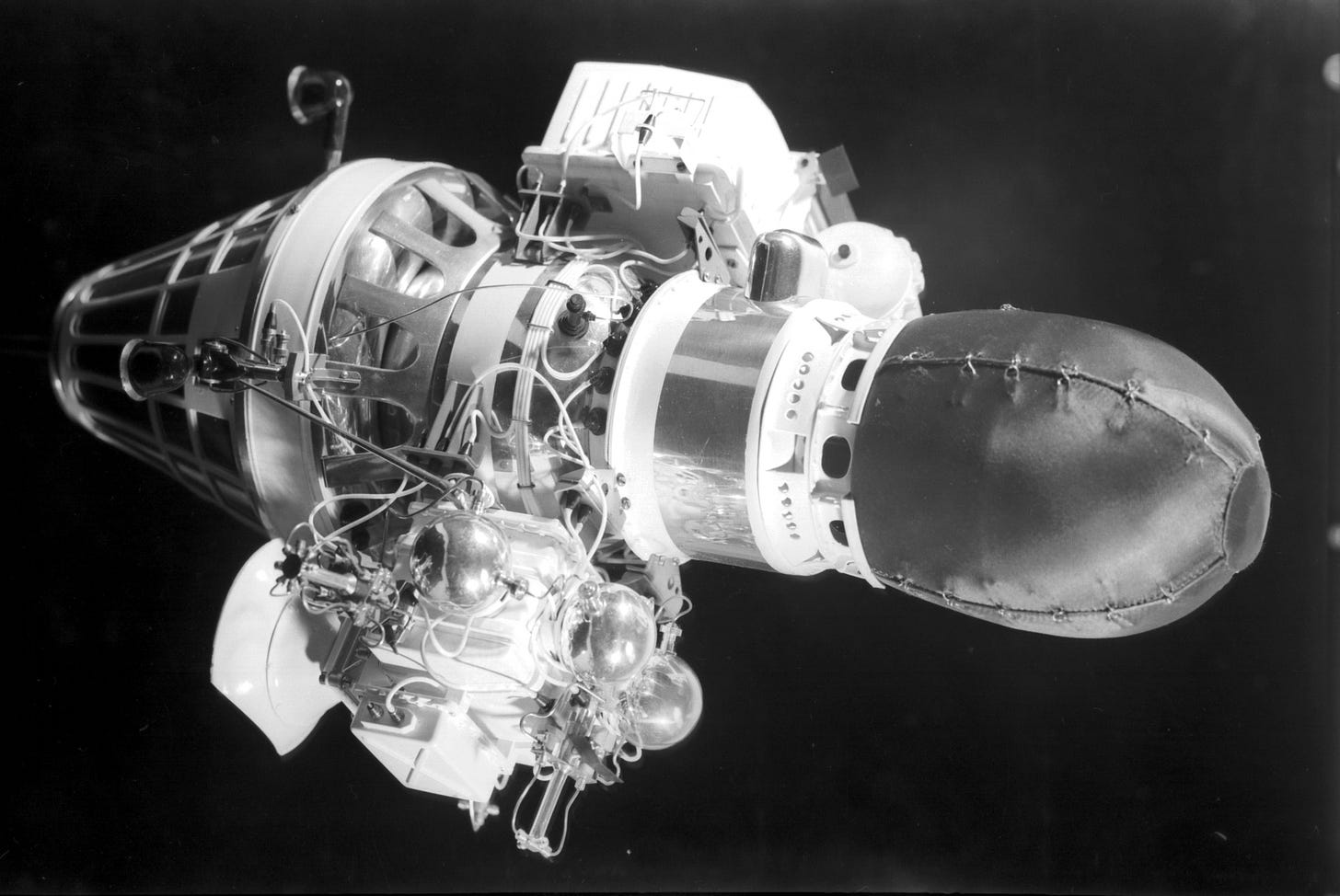
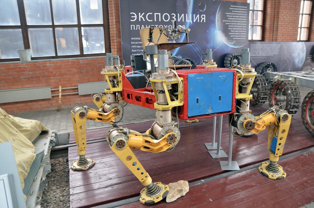
This Edition’s Cool Image:
This Edition’s Cool Link:
Space, and other special equipment in the Technical Museum, Togliatti
Now your going to need to read Russian or use computer translation, but this is one for the more serious researcher. All sorts of unusual photos and details when you explore this site!


I think we need a poster showing all known (built and proposed) manned lunar landers from the BIS 1947 on. Not Science Fiction just fractural subjects.
The 19k21k design is interesting because it suggests the Soyuz design has an exceptional margin for lateral stress. If that’s so, how’, and has it carried over to today?