

Understanding the LKM/L3M/LKE
The various advanced landers, and my approach

Overview, almost all the crewed modules.

The number of lander designs considered is really quite spectacular. And as usual, the references are incomplete, and contradictory. This post will explore how I tried to make sense of them, to work on the models of the LKM and D2.
Along the way I will explain the functions of the various elements.
For a previous article on other aspects of the N1 based missions, see this previous post.
Terminology
The LKM and L3M names seem to be used interchangeably. Now, the M indicates “heavy”, (I think of it as “massive”), so perhaps these terms refer to the heavy version of the LK lander, and the heavy version of the L3, the combined modules on top of the N1? But I see no sign of that distinction in the usage…
And, just to add to the fun, the Cyrillic “3” is so similar to a Z, you will even see Russian sources call it the LZM.
LKE refers to the expeditionary versions of the LK, which would have been launched on the Vulkan Superheavy, which was then scaled back for Energia launching.
It is striking how similar at first glance these different heavy versions look. This despite the fact the the L3M / LKM was designed before Glushko took over. My suspicion is that Glushko was not very interested in payloads, and so didn’t bother ripping up the lander designs, and starting again. Unlike the rockets…

GB1 and GB2. These terms appear in some of the declassified documents, and they refer to the 2 different payloads for the twin launch missions.
Головной блок 1, Головной блок 2
Galavny block 1, Galavny block 2
Head block 1, Head block 2.

The upper stages were different, and you will also see references to Block SR and Block D2.

Block SR was an advanced hydrogen upper stage, and was a key development required for these missions. It would handle getting the required modules to the Moon.

D2 was an upgraded Block D, more powerful. As you can see in the diagram above, at least 2 different D2 versions were considered. I have used the one on the left, as more details are provided, and I therefore consider it likely it was better developed than the longer version.
When a more powerful Block D was finally developed, it was Block DM, again M stands for Heavy, and this served for many years as an upper stage.
A previous post provided diagrams of D2 and SR blocks.
Lander Source 1. RKK Energia Encyclopaedia.

The first volume of the RKK Energia Encyclopaedia covers several designs, but only the expeditionary versions. Nothing from Vasily Mishin’s bureau. But they help us distinguish between expeditionary versions, and the various “heavy” versions.
Lander Source 2: RGANTD references
Of course, information from the state archive is generally definitive, but often incomplete. We have a few documents, and, as usual, there are contradictions.

Conclusion: The main visual distinction is that the base of the expeditionary landers was much thicker vertically.

Source 3. Moscow Aviation Institute mock-up.

I say mock-up, it’s so basic it hardly deserves the name. Mentioned here for completeness.
Source 4. Kirov Museum Model.
There’s a model of an LKM / L3M in a museum in Kirov, and photos from many angles are available. Hooray! But…
There are clear issues, to the point where some authorities dismiss it completely. I think this may be a bit hasty, particularly as a good 3d version of ANY lunar craft is so difficult to get.
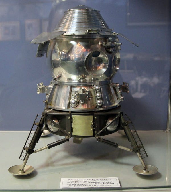
So, here are some of the issues you may have spotted.
Some sort of docking flaps around the base engine. These make no sense.

Note the 3 flaps, centre and underneath No airlock - though there is a “stalk” where it goes? And a space on the conical part.
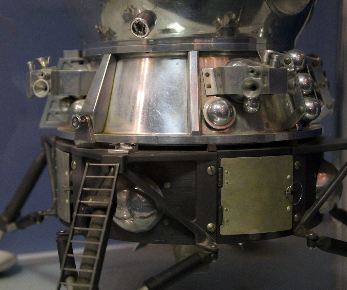
Gap between a “spout” and the ladder There are 2 ladders on the legs. Does this make sense?

Two ladders. Note the basic rover, left! Does this go opposite the airlock? One of these ladders is in front of the windows, which seems a weird place to put a hatch. And there is not a hatch there in any illustration I can find.
Some features are distinctly chunky, maybe we can’t trust fine detail. To state the obvious, I don’t think the legs were attached with giant screws.


So, here are my working assumptions after thinking about this:
At some point the model was disassembled, a few bits were lost, others were put together incorrectly. For example, the D2 block »DID« dock with the base, but not onto the engine.
If you rotate the ladders around to the next leg, you end up with one under the airlock, and one at the rear, where RGANTD diagrams show a simple hatch! This makes sense to me.
And in case you are wondering, the flaps at the top are radiators, other illustrations show them with pipes running over the surface.
The Result!
I always end up tweaking models and renders, and of course, there’s the hope that new info comes out. So it’s never actually final, but here’s an animation of the model I built after this analysis.
I made two versions, one with the legs stowed, and one with everything in the landed and deployed configuration.
Some notes on the result.
I’m really happy with this result, considering the information I had available.
For the airlock, I think the simple hatch at the rear must have been a backup, in case there were problems with the main airlock. Not only does it line up with the second ladder, note how the rods between the battery racks now make sense! These would function nicely as a ladder, for the cosmonauts to make it down to the main ladder, on the leg.
This kind of discovery is the sort of thing that makes modelling these craft so rewarding, by trying to build a full 3d model you are forced into understanding the elements, and thinking about how they work together.
I really think the gap on the conical section opposite the airlock would be good for stowing a folded-up Apollo style crewed rover, like the vehicle shown in the Kirov museum display. And the gap under the cabin windows makes sense if you want the crew to have a clear view for landing.

I chose the “tub” airlock, mainly because I have stowed and deployed versions, and I have no idea how the spherical one would be stored during flight, or under the fairings.
Block D2.
As mentioned further up, there are two versions. Here’s the longer version attached to the LKM.

And here’s a spin of my “finished” model, shorter D2 version:
And a spin of the LKM and D2 docked.
I plan on doing some fine detailing of block D2 at some point, but I wanted to show you what the result of all this analysis was.
Mission Architecture

Three different mission profiles were considered.
Single ship, direct return. Everything on one launch has serious weight considerations.
Dual launch, single ship. Two larger vehicles can be sent to the Moon, to dock in lunar orbit. Direct return. This is the main option that seems to have been taken forward.
Dual Launch, to ships. This, somewhat like the L3 missions, has a separate LOK Lunar Orbiter, and has a docking in lunar orbit before the return to Earth.
Note that the ascent stage heading back to Earth has solar panels shown.
That’s it for this edition - I made it longer than usual, and had more of a mix of CGI and references, let me know in the comments what you think.
And a reminder that if you like more frequent info, I post frequently on Mastodon and Blue Sky.
https://bsky.app/profile/nick-stevens.com
https://mastodon.art/@Nick_Stevens_graphics
You don’t need to sign up to either service to see what I have posted.
This Editions Cool Link:
The best regular update on the current exploration of the Moon is Jatan’s Space. He’s particularly strong on what’s happening with smaller nations, things you may not read about elsewhere.

This Editions Cool Image:
I’ve not yet worked through the translation, but here’s a really nice RGANTD reference I upscaled, showing 5 versions of the LKM, with their capabilities.

This Editions Cool Download:

As usual, the download is available for 1 week only. “Russian Space” magazine from 2019, with an article on “Collected Cosmic Rarities” that includes lunar exploration material.
Do we know why they included an airlock in this design? The LK was meant to depressurize so presumably they had solved their electronics-cooling problems well before the LKM was to be in service.
Nick I wish there was a translation of Mishin's notes somewhere!