


N1M, Illustrations and technical details at last!
The heavy version of the N1 is dragged into daylight!

Note from Nick - this is a LONG post, with LOADS of new information! I hope you will read the whole thing, I think it’s the most data I have ever published in a single substack.
Advanced N1 designs
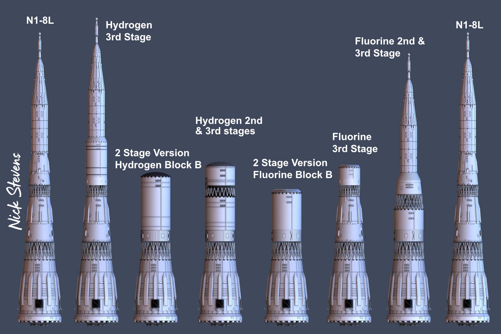
The later designs of the N1 can generally be gathered under N1F for the flight version, or N1M for a future heavy version, using advanced fuels. The N1M in particular seems to have been so vaguely described that it’s more like a family of loose ideas. The only illustrations I have seen until now were no more than outlines sketched for different fuel combinations, uncovered by Pavel Shubin.
“until now”
Two illustrations appeared on Russian space forums, and at reasonable resolution too! I’ve cleaned them up, and run them through AI enlargement, (which generally works well on diagrams).
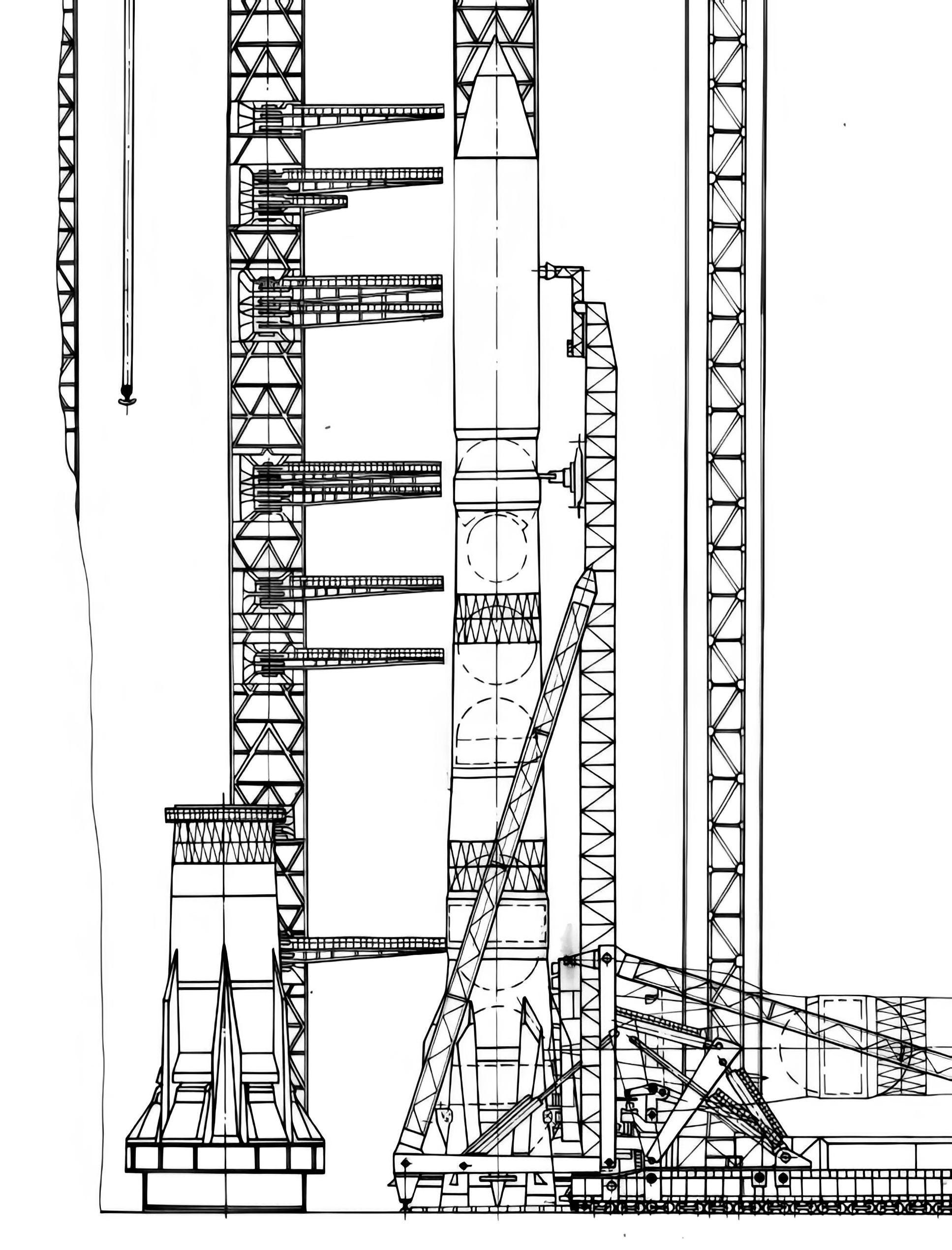
So, WTF is going on here?!
Some notes:
What on earth is going on with that first stage / block A? A much wider base? Bracing connecting that base to the main body of the first stage?
The fuel tanks - note how some spherical tanks have been extended, with the addition of a cylindrical section around the equator.
The upper tank on the 3rd stage is really weird, with an indentation to fit around the lower tank, and wide enough that the 3rd stage hull needs a wider section.
The service extensions from the gantry tower are different - I suspect they were always designed to be able to move up and down, to fit different designs. They are a different shape as well though, in this case.
The tall tower to the right is presumably the lightning protection system, and I’m guessing that is unchanged.
And here’s the second new illustration:
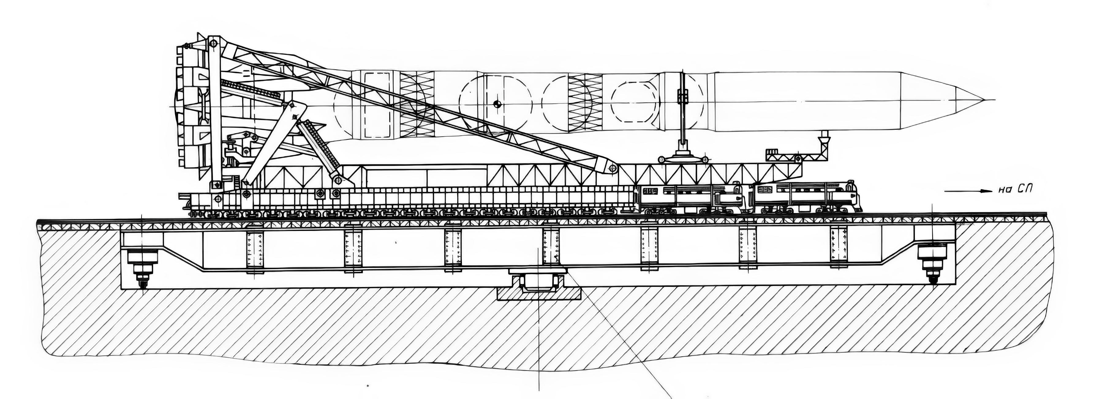
This one is, if anything, even more intriguing.
The grasshopper transporter has been extended considerably.
Look at all those extra wheels / bogeys! Not so much a grasshopper, more like a millipede. How much heavier is this beast?
The extended tanks are shown more clearly in this view.
I’m guessing from the underground detail that the foundations under the tracks need upgrading.
Note that the railway system for rotating the huge launch tower required major innovations in rail technology, to handle the extreme weight.
But the thing that interests me most is the first stage - this looks different from the other picture. And it looks for all the world like 6 Soyuz type booster stages have been attached!
Now, this seems to contradict all the written descriptions, and it’s worth saying that people who know more than me think it is not what it appears. It’s more likely to be an alternate engine arrangement, or a new design for fuel line covers.
But those small triangular fins are SO Soyuz!
Oh for a diagram with a clear view of the base!
Grasshopper comparison:
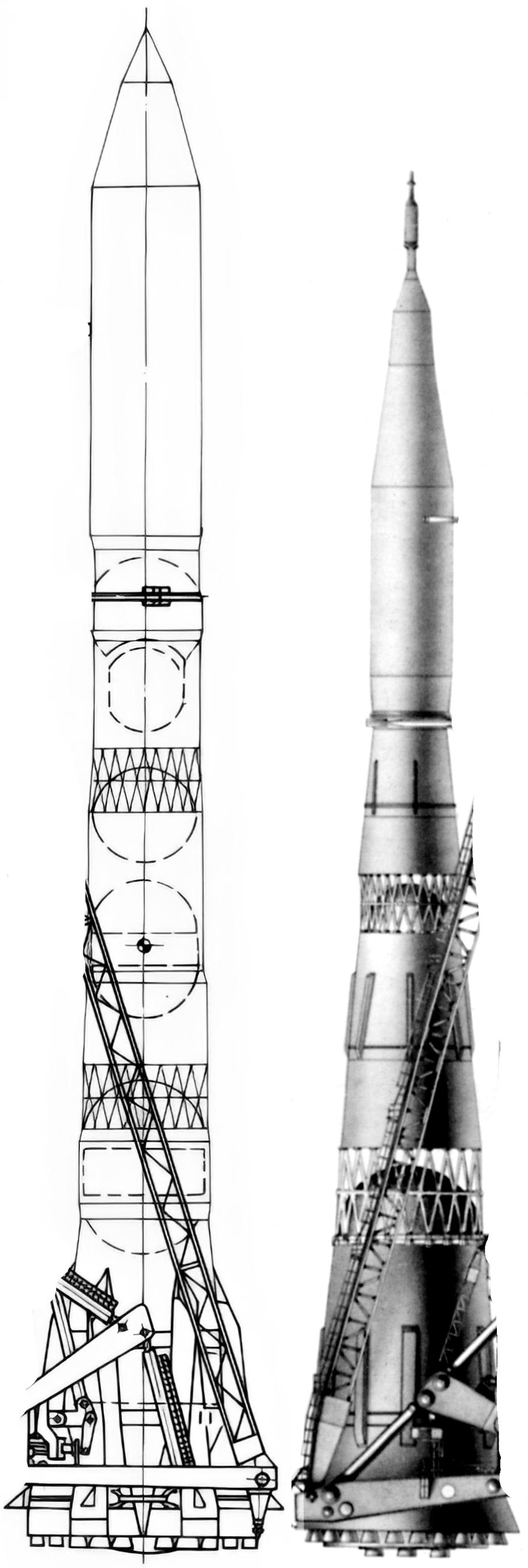
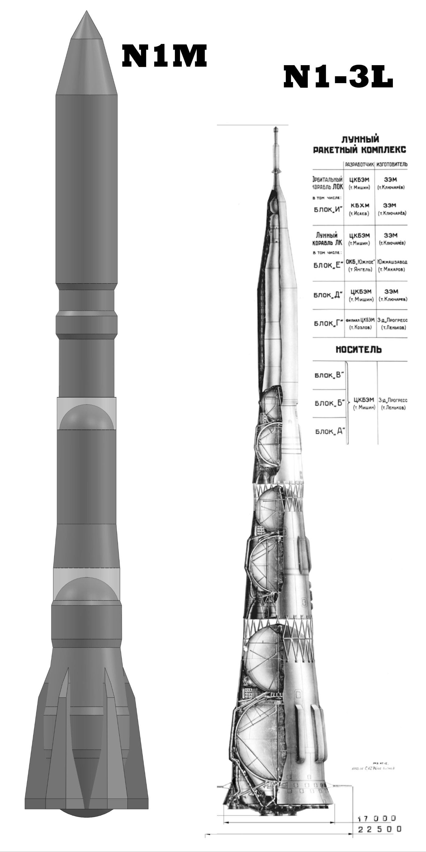
Here’s a diagram I made combining the N1-L3 version of the Grasshopper with the N1M version. I scaled them by matching the size of the locomotives.
We can also use this to get a (very) rough view of the N1-3L next to the N1M:
N1M, A technical description:
Yury Shakhov has published a description of the N1M online. The details are many, and dimensions are precise, which give it credibility. I’ve provided a DEEPL translation of the whole thing, so brace for a big chunk of text. I’ve included this in full, given it’s importance.
At one time Korolev foresaw broad prospects for the use of oxygen-hydrogen fuel in rocket and space technology and envisaged its widespread introduction on modifications of the 11A52 launch vehicle.
If not to look back at numerous concepts, the apotheosis of the CCBEM's plans for a launch vehicle using high-energy propellant was the N-1M, the preliminary design of which was released in May 1969 with more than 20 volumes of design documentation.
The developed layout scheme took into account the experience of production of 11A52, technological capabilities of enterprises, mastery of technological processes, availability and possibility of manufacturing special equipment, and also took into account the specific conditions of manufacturing of the carrier.
‘Emka’ differed from the 11A52 by increasing the working reserve of fuel in Blocks A and B and the use of hydrogen/oxygen fuel in Block M (replaces Block V), the use in the design of boosted (up to 154 tonnes) engines 11D51 with an increase in their number in Block A to 36 pieces, the use in Block M up to 6 engines 11D54 with a specific impulse of 456. 5 sec and thrust of 40 tonnes in vacuum (image No. 2); Increase of loads on blocks, change of layout, geometry and design of compartments and units; Application of materials D20-1, B-95, BT-6S, BT-14 in the design of fuel tanks of hull units and inter-block trusses. Due to all the changes the payload of the booster increased up to 150 tonnes to LEO. Further more detailed information on each stage is given below.
Block A.
In the oxidiser and propellant tanks introduced cylindrical inserts consisting of panels of waffle design, made by milling from a plate of material D20-1 (for the tank ‘O’ insert length 4350 mm, for the tank ‘D’ - 3600 mm), spandrels with a maximum height of 900 mm and transition compartments (‘skirts’ of tanks) of rivet-welded design of titanium with a height of 1000-1200 mm for tank ‘O’ and riveted design of aluminium alloys with a height of 800 mm for tank ‘D’.
Cylindrical inserts, spandrels and transition bays are included in the power scheme of the block hull.
The geometry and design of the intertank compartment has been changed. The height of the compartment is 9100 mm (on 11A52 - 13305 mm). The diameters of the compartment: in the lower part is 12790 mm, in the upper part is 10360 mm (on 11A52 respectively 13850 and 10962).
Developed a new layout and design of the tail compartment of the block.
The engines are mounted on power panel trusses of 6 pieces, which are arranged in a star-shaped pattern around the circumference of the tail section slice at 60° intervals. The engine mounting trusses are connected by an internal power unit type A7130-0 11A52 and external power units on each truss. At the top, the power units are connected to the power ring, forming a power triangle in cross-section. An oxidiser tank is mounted on the upper power ring (the apex of the triangle).
Changed the design and geometry of the transition launch ring, introduced special compartments (bollards) to attach the unit to the transition launch ring.
Changed material to BT-6C or BT-14 and increased diameters of interblock truss rods to 280-300 mm.
The overall dimensions of the block increased and are: height 36950 mm (on 11A52 - 28310 mm), the dimeter of the block at the bottom cut 22500 mm (on 11A52 - 16875 mm), the diameter at the top cut 10260 mm.
Block B.
The tank mounting scheme is suspended. Increase in working fuel reserves made on the oxidiser tank by introducing a cylindrical insert in the tank, made of smooth shell thickness of 20-30 mm and height of 3300 mm. On the cylindrical insert in the lower part of the welded suspension power units.
The tank is attached to the power ring by means of a titanium truss. The volume of the fuel tank is increased by increasing the diameter of the tank, which is made in a lentil-shape with the bottoms connected by means of a spar.
The tank bottoms (with a sphere radius of 4185 mm) are borrowed from the 11A52.
The geometry and design of the inter-tank compartment has been changed. The height is 12650 mm (on 11A52 - 8765 mm), the diameter of the compartment is 9100 mm.
Increased diameter and height of the inter-bay truss, which are 9100 and 5000 mm, respectively.
The diameters of the truss rods are increased to 260 mm, the truss material is changed to BT-6C or BT-14.
Tail compartment is structurally similar to the tail compartment 11A52. Reinforcement of the compartment frame was made.
The overall dimensions of the block increased and are: height 25145 mm, diameter at the bottom of the block 10260 mm, the upper cut-off - 8500 mm. (On 11A52 respectively 20461 and 10260 mm).
Block M.
The Block consists of:
ㅤ1. A tail compartment with a height of 8930 mm and a dimeter of 8500 mm, structurally similar to the tail compartment of Block B 11A52.
ㅤ2. Rings-ferms for the installation of 6 engines 11D54.
ㅤ3. Oxidiser tank made similarly to the oxidiser tank of Block B 11A52 with the additional introduction of a cylindrical insert and 2 special spandrels.
ㅤ4. Fuel tank, consisting of a top bottom R = 4185 mm, power belts made of milled panels of alloy D20-1, cylindrical insert height of 2400 im and the lower concave bottom R = 4185 mm waffle design with a rib height of 60 mm. The cylindrical insert and the power belts are included in the force diagram of the hull.
ㅤ5. Tail section attached to the oxidiser tank power belt.
ㅤ6. Instrument compartment riveted construction height of 3200 mm and a diameter of 9500 mm. The overall dimensions of the unit: height 17500 mm, block diameter 9500 mm.
Documentation and manufacture:
The new layout and design of units and blocks required new development of design documentation and accordingly new preparation of production and mastering of new technological processes.
The manufacturing technology is characterised by the following main features:
ㅤ1. Large size of units and blocks.
ㅤ2. The use of power cylindrical inserts in the fuel and oxidiser tanks, made of milled panels with stiffening ribs. Panel wall thickness ~20 mm, with stiffening ribs up to 60 mm, panel height 4500 mm, width 1800 mm.
ㅤ3. The use of power spandrels in the fuel and oxidiser tanks.
ㅤ4. By the use of special profiles and stampings.
ㅤ5. The use of large thicknesses of sheet materials (up to 50-60 mm).
ㅤ6. Application of special heat-protective and heat-insulating materials.
ㅤ7. Application of new types of materials (D20-1, BT-6C, BT-14, BT-95).
ㅤ8. Application of fittings operating in supercooled hydrogen medium with large cross-sections and high flow rates.
Technological peculiarities of the carrier determined the necessity of development and mastering of new technological processes:
ㅤ1. Pressing of large-sized profiles, large thicknesses and layered sections.
ㅤ2. Casting of assemblies from new grades of materials.
ㅤ3. Moulding of special large-size profile ribbed panels.
ㅤ4. Machining of special spandrels, ribbed panels and profiles.
ㅤ5. Automation tests with special equipment.
ㅤ6. Welding of large thicknesses of spandrels and ribbed panels.
ㅤ7. Welding of tanks with cylindrical inserts and power spandrels.
ㅤ8. Welding of new types of metals, including D20-1, BT-6C, BT-14, etc.
ㅤ9. Welding of pipeline joints.
ㅤ10. Machining and bonding of honeycomb sets.
ㅤ11. Manufacturing of in-tank systems operating in subcooled hydrogen environment and other processes.
Assembly Location
Due to the non-transportability of units and blocks, and based on the experience of production of 11A52, the technological process of production of H-1M provides:
ㅤ1. Complete manufacture of assemblies, systems, transportable elements of tanks, units at manufacturing plants.
ㅤ2. Assembly and mounting of aggregates, units and carrier at the technical position,
ㅤ3. Welding, testing and assembly of tanks at the technical position
The technological process of assembly of units and blocks at the technical position provides for:
ㅤa) bench assembly of units and unit compartments;
ㅤb) final assembly of the unit vertically;
ㅤc) docking of Units A, B and M and their testing vertically in special stands with external maintenance facilities.
This is the most valuable information that could be extracted. Unfortunately, out of more than 20 volumes, only two have survived to date - the volume with technology issues, and the volume with the selection of communication lines and antennas. To my great disappointment, there are no visualisations of this monster in them.
In addition, the fate of the carrier remains unknown to this day, because within the framework of the L3M programme it was planned to use the same oxygen-kerosene 11A52, but with the replacement of paraffin with synthine in Block B. With such an upgrade, the payload on LEO would increase from 90 to 103 tonnes.
A few key points I noticed:
36 engines on Block A!
Payloads of 150 Tonnes to Low Earth Orbit
Block V (Third Stage) completely replaced.
Phew! Congratulations of you made it this far… We are not done yet!
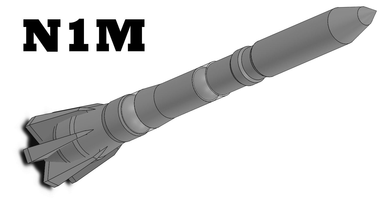
N1M, by “Hahaha”
In case you think I have gone mad, “Hahaha” is an onscreen username in a Russian space forum! He has also been digging into the N1M and modelling it, this is what he has come up with:
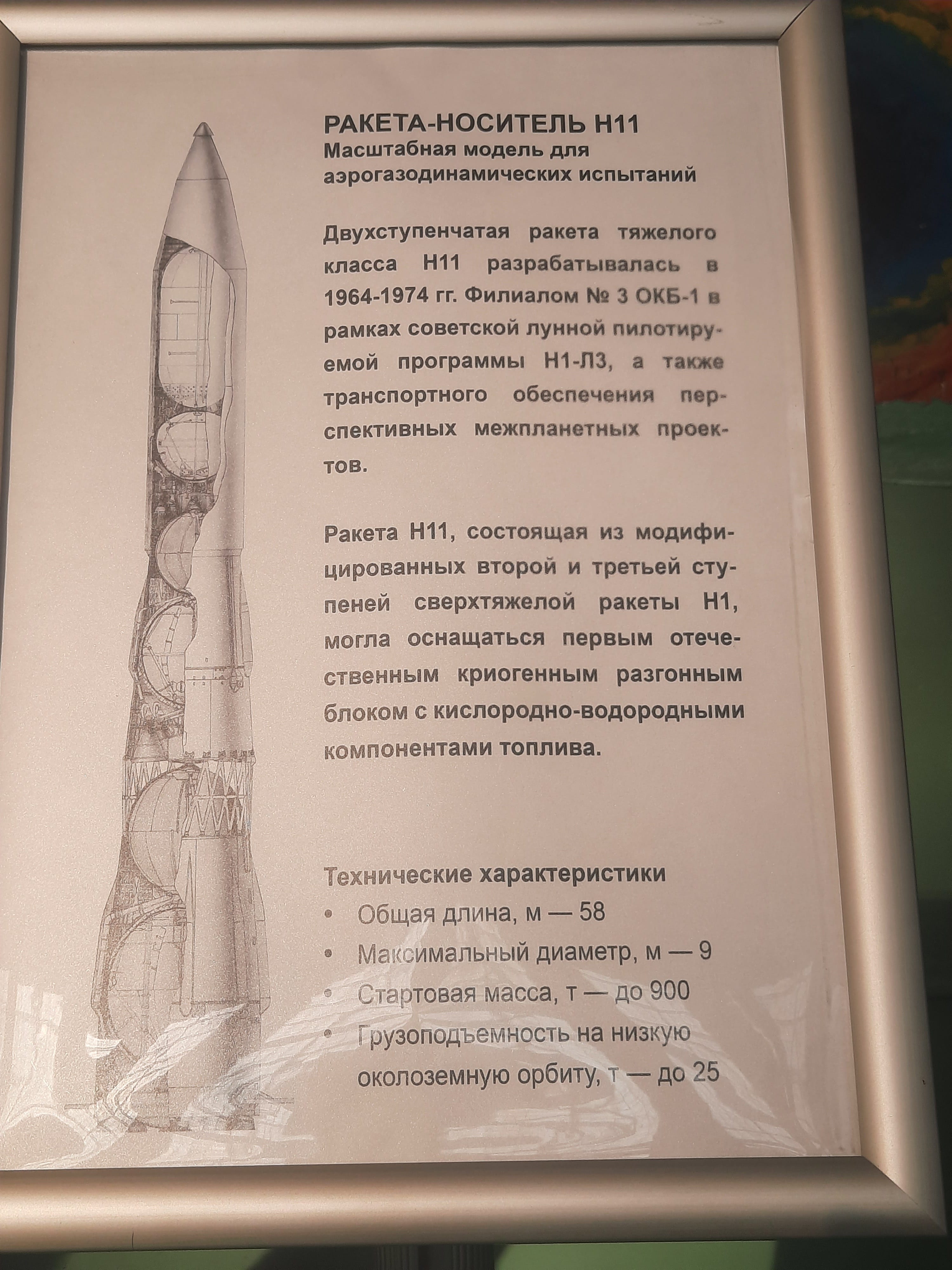
N-2 / N-11 model in the Moscow Aviation Institute
The N-11 was a Proton class launcher based on stages 2 and 3 of the N-1, it never left the drawing pad. But there’s a strange model in the MAI!
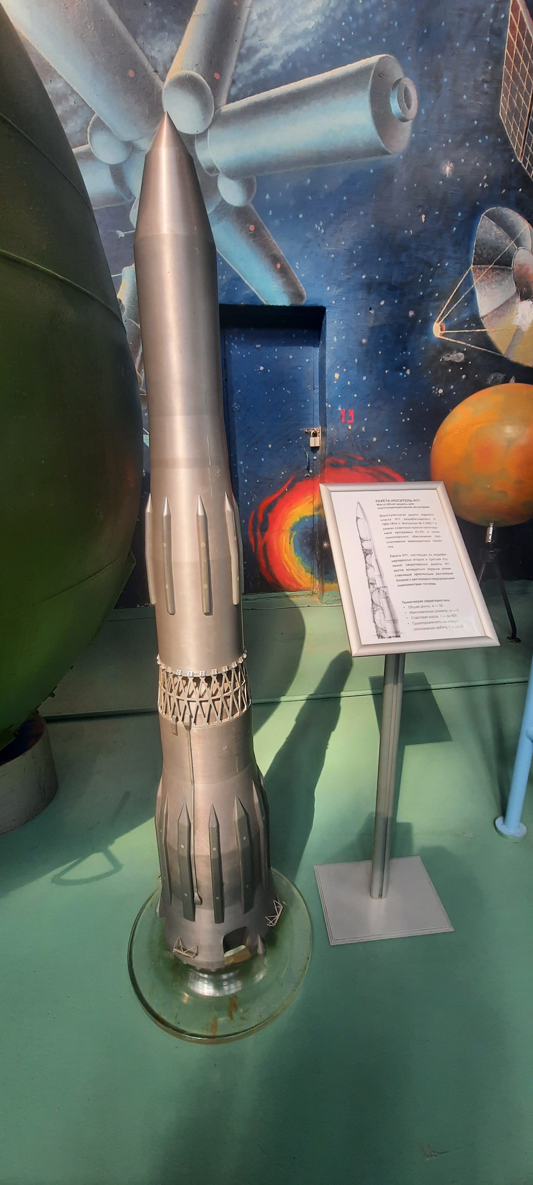
Now the accompanying document, to the right (included below), refers to this as the N11. But… The model doesn’t match the illustration on the placard!
The model is clearly the first two stages, not stages 2 and 3. The streamlined fuel line covers, (on the model and the placard), clearly indicate N1-7L variant, or later. The model is clearly damaged, with grid fins missing, and a hole in the side.
What is going on? That is not (yet) clear. But it does show that serious consideration was given to reviving the N11 in the seventies.
It also shows how even the foremost museums in Russia seem to do a terrible job of understanding what they have, and how careful you must be when assessing information on this subject.
On the metal model “simonbp” suggests:
“It looks like a wind tunnel model (since it's steel). Wind tunnel models at that time would have dozens of diaphragms with tubes running out to mercury barometers. There would be two guys at each barometer, one calling out numbers, one recording as fast as he could!
So it's possible that the hole is for getting more pressure tubes out.”
Which makes sense to me.
OK, that’s it for this post, thank you for reading this far.
This edition’s cool link:
Anatoly Zak has uncovered details of the N1 crew escape system, (SAS)
https://russianspaceweb.com/l3-sas.html

This editions cool image:
Click for an even larger version!
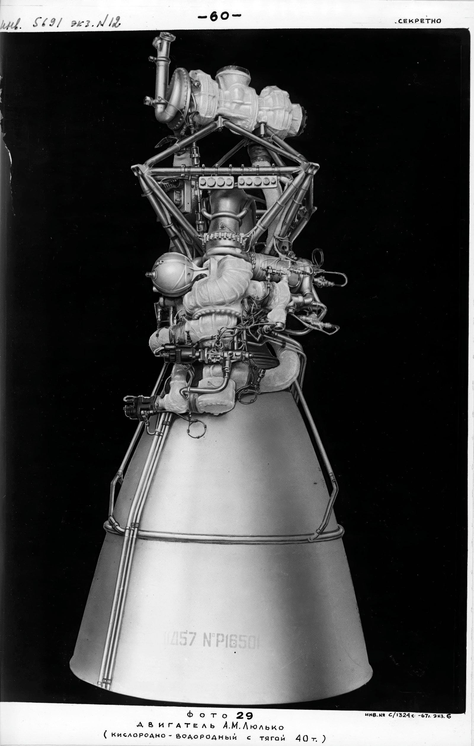
Mark Wade describes the engine here: http://www.astronautix.com/r/rd-57.html
Lyulka LOx/LH2 rocket engine. N1 Block S (N-1M). Study 1965. One to have been used in N1 Block S. In fixed chamber version, 3 to 6 to have been used in N1 Block V-III. Engine system includes roll control thruster with 1.29 kN thrust.
AKA: 11D57;D-57. Status: Study 1965. Date: 1960-77. Thrust: 392.00 kN (88,125 lbf). Unfuelled mass: 840 kg (1,850 lb). Specific impulse: 457 s. Burn time: 800 s. Height: 3.66 m (12.00 ft). Diameter: 1.86 m (6.10 ft).
Engine: 840 kg (1,850 lb). Chamber Pressure: 111.00 bar. Area Ratio: 142.3. Thrust to Weight Ratio: 47.61. Oxidizer to Fuel Ratio: 5.8.
This editions 7 day only special download:
Another very special one, a technical document on the development of hydrogen engines for the N1. Russian language, (of course). I’ve also added the original Russian description of the N1M, as a text file.
Click to download, 7 days only.

I will work on translating and analysing it for a future substack post.
Собственно, как раз таки я написал ту статью с техническим описанием Н-1М. Грубовато, но вполне себе неплохо получилось.
Что могу отметить - на первой схеме, предоставленной товарищем Шамсутдиновым, Н-1М находится не на стартовой позиции. Носитель предполагалось собирать вертикально, а на схеме он как раз расположен в МИКе
Thanks for these very intersting documents.
I like to pecise that the engines was desinged by Nicolaï Kouznetsof by claim from Sergueï Korolev.
These engines was working with closed cycle and this type equiped today tho most number of rokets.
Bests regards.
Eric Delcamp