

N-1, New Hardware Reference
New photos of the 2nd and 3rd stage, info on the L3

Hello, and welcome to this N1 focussed post. In it we will cover the structure of the N1 second and third stages, (Blocks B and V), collected photos of Block G, and a revelation of what the wedges are on the L3 inner hull!
Many new photos, and photos I’ve had for a while, but could not share.
Be aware that these photos do not have proper context yet, and should therefore be treated with some caution.
Engine frame for 2nd and 3rd stages.
Horrible halftone artefacts, which I tried to clean up here:
Here’s another, a bit soft, but better.
Notice the irregular pattern of the small struts, with some gaps! This had me really confused when I built the first model, until I realised they were perfectly placed for the engine fuel lines.
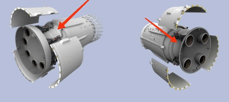
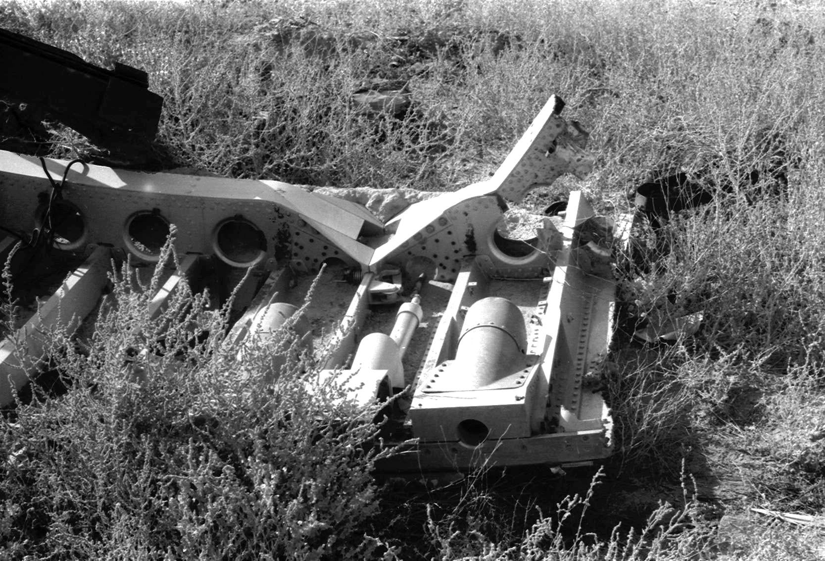
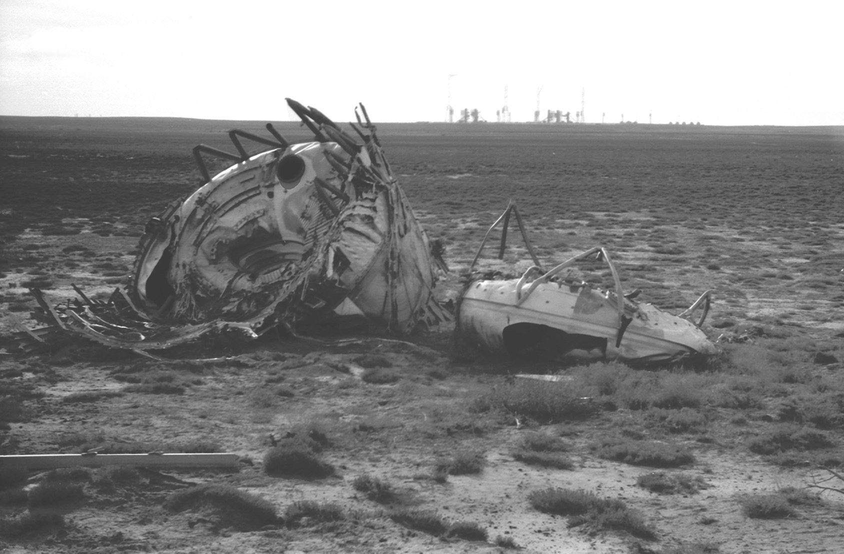
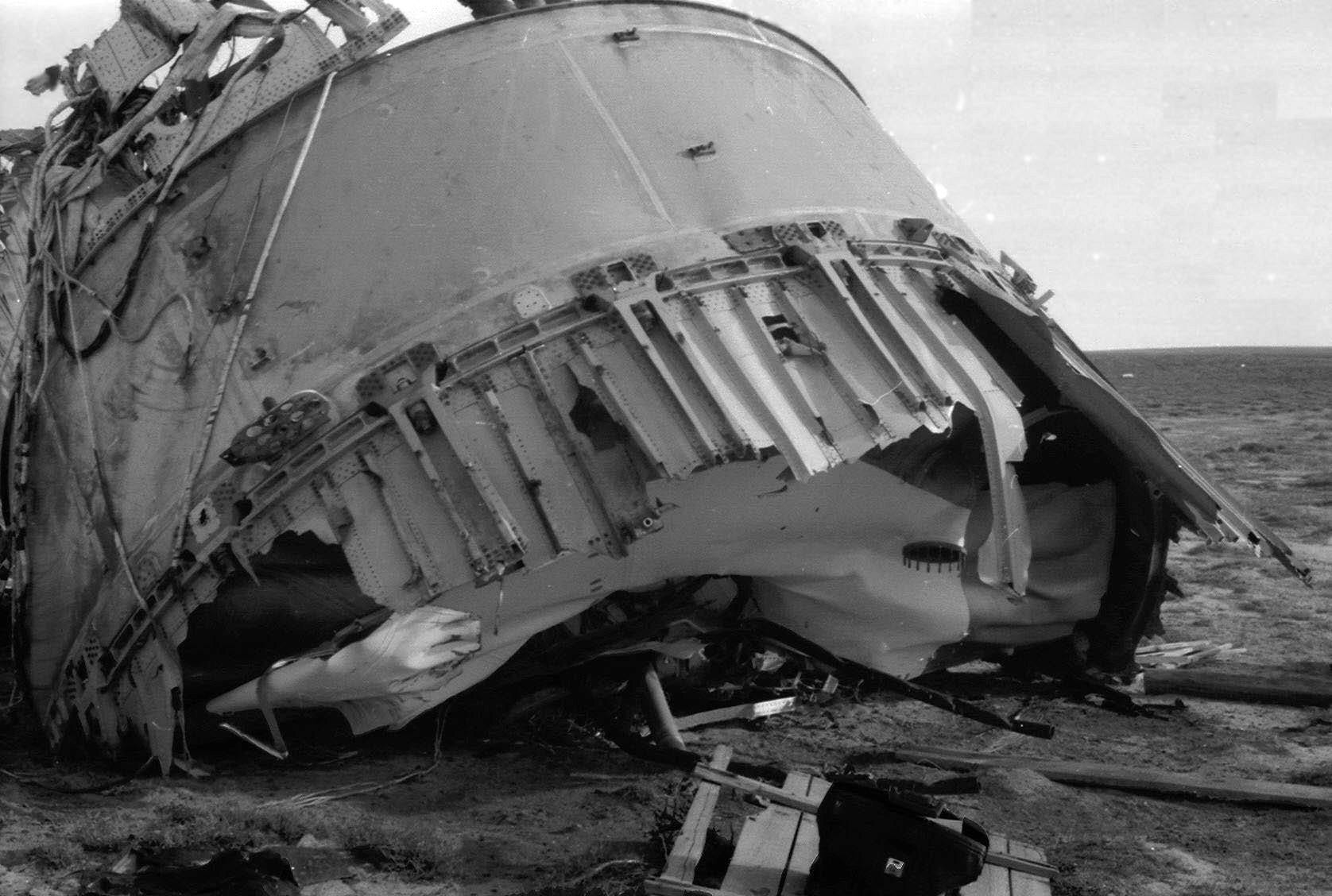
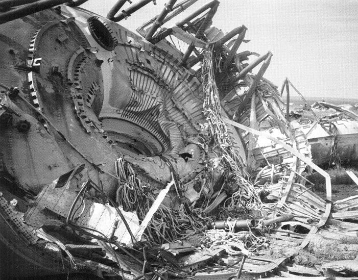
The engines in both cases seem to be mock-ups, so these shots are probably of the weight model. Here’s a lovely photo by Vladimir Antipov of the same section from the wreckage:
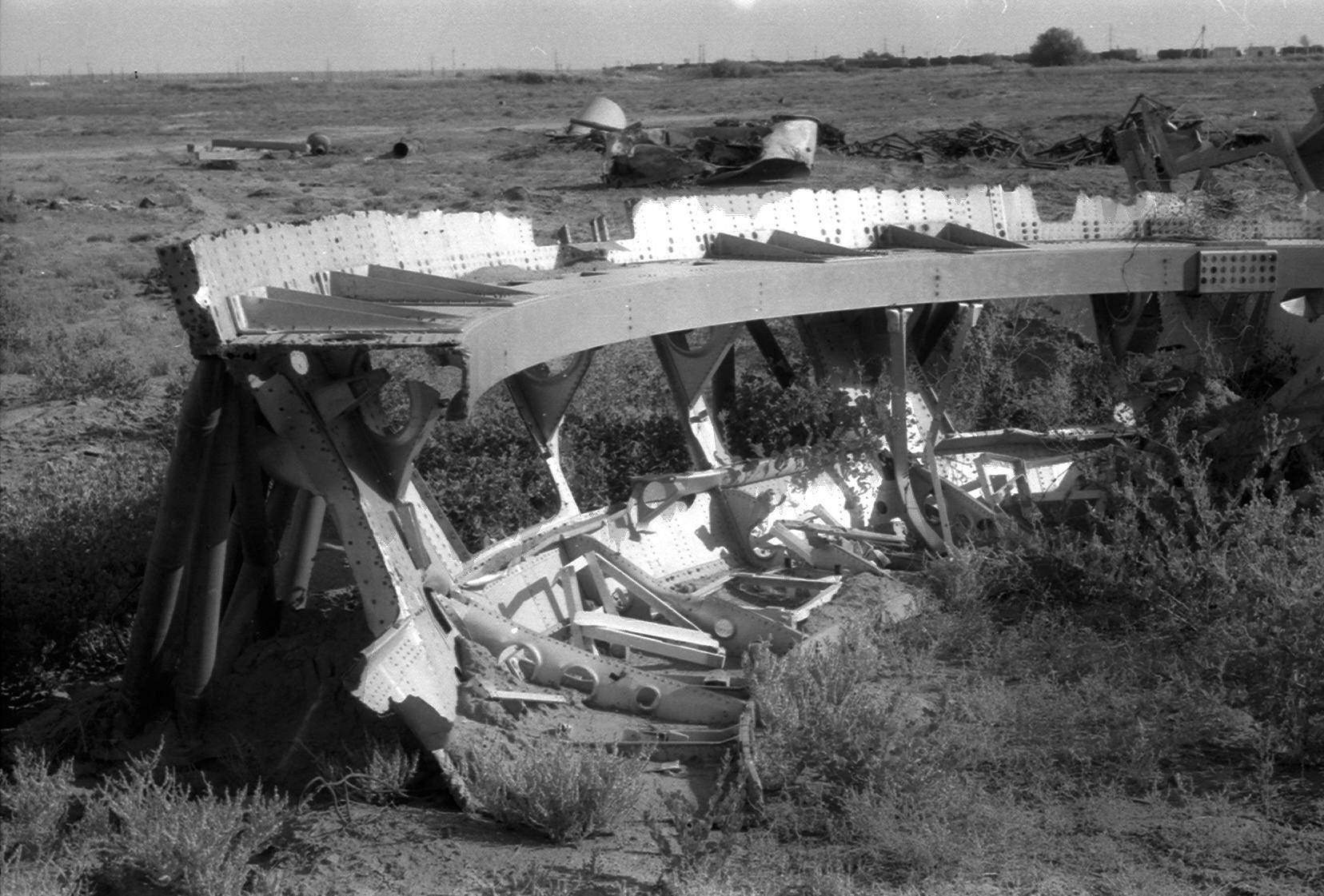
Please note I have not enhanced or enlarged Vladimir’s photos, in a couple of cases I stretched the contrast, but that is the limit of my processing of his work.
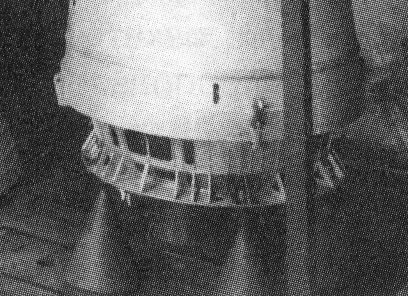
Let’s move on to the fairing ejection system.
N1 Fairing Ejection:
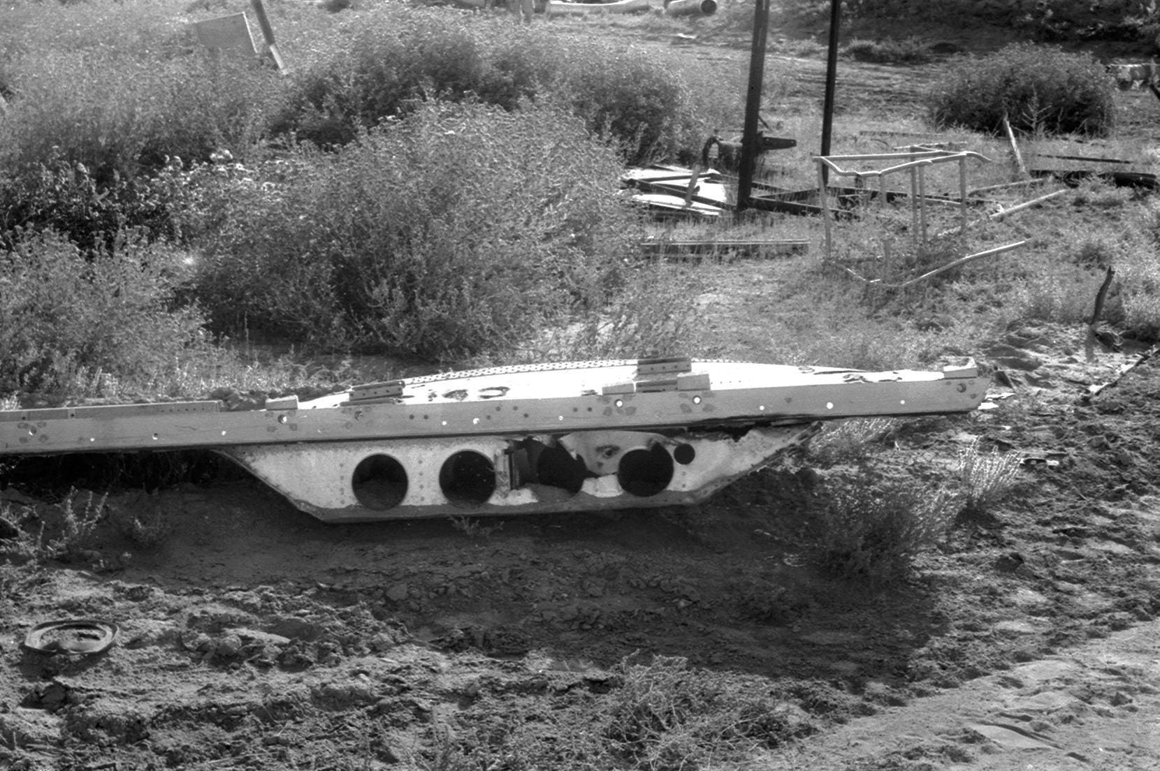
I previously thought that the fairings were ejected using the sets of small rocket on each section, as shown on the wreckage section above. And in the following photo:
But it seems there’s a bit more to it…
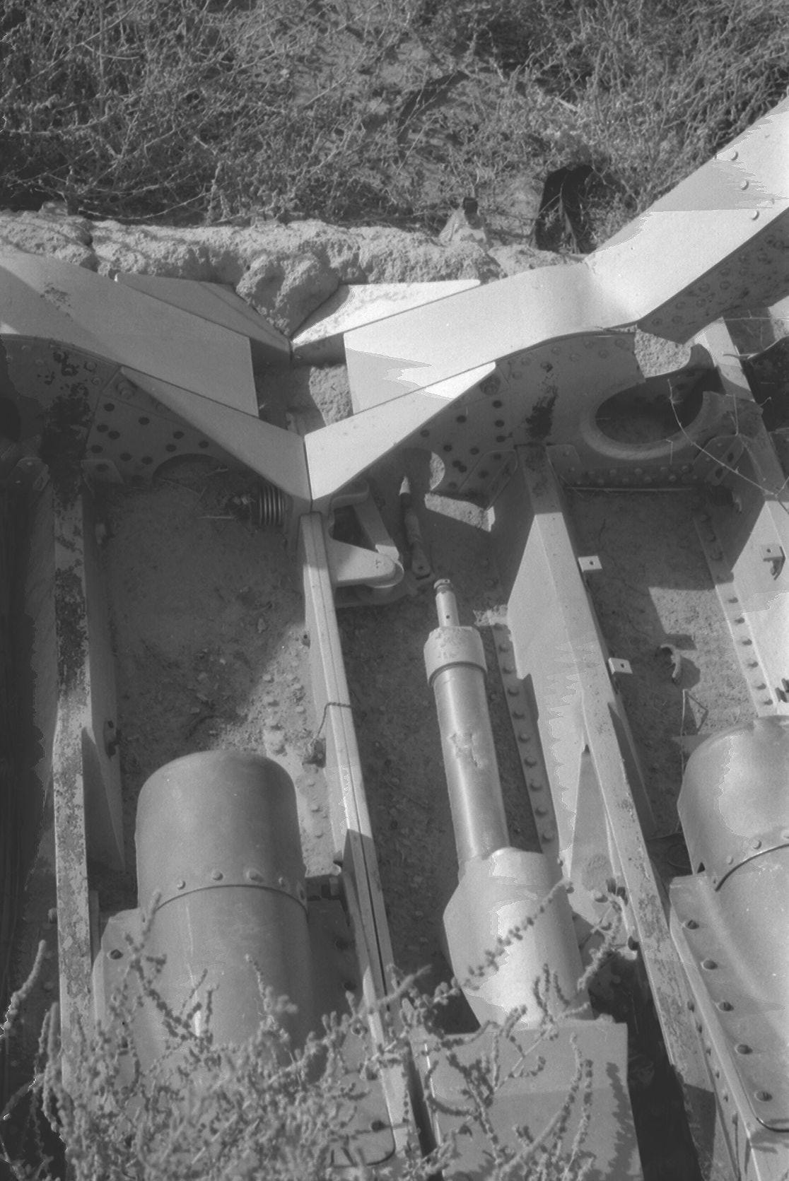
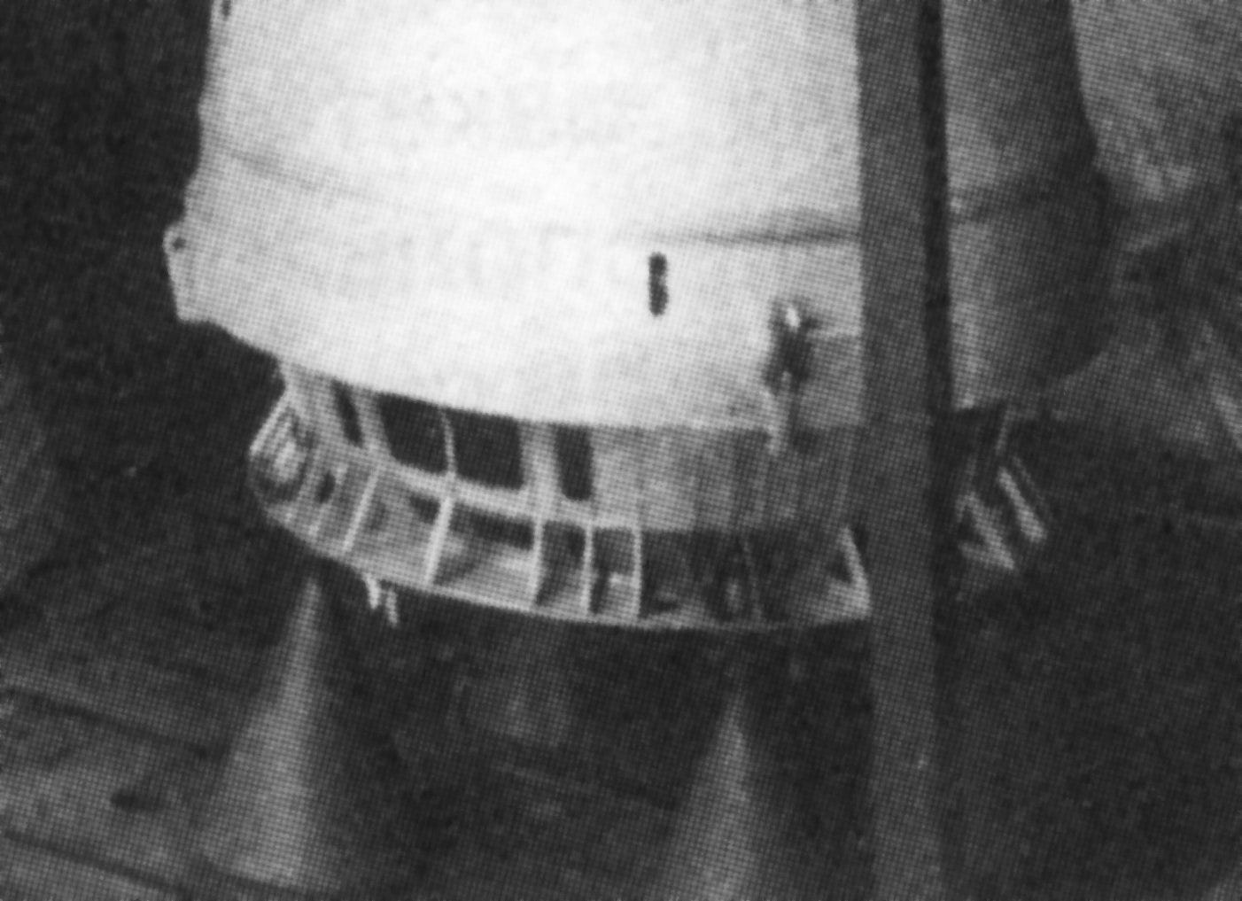
This is completely new to me - it looks like pistons, to push away the sections of fairing. “Tail section flap release mechanism” is directly translated from the Russian. But it’s not clear to me exactly where these are located. Here’s another photo of the same area.
Now, without more context, and a location on the hull for these parts, it is unwise to take these photos at face value. So stay tuned for further analysis, and subscribe to this substack!
L3 spacers.
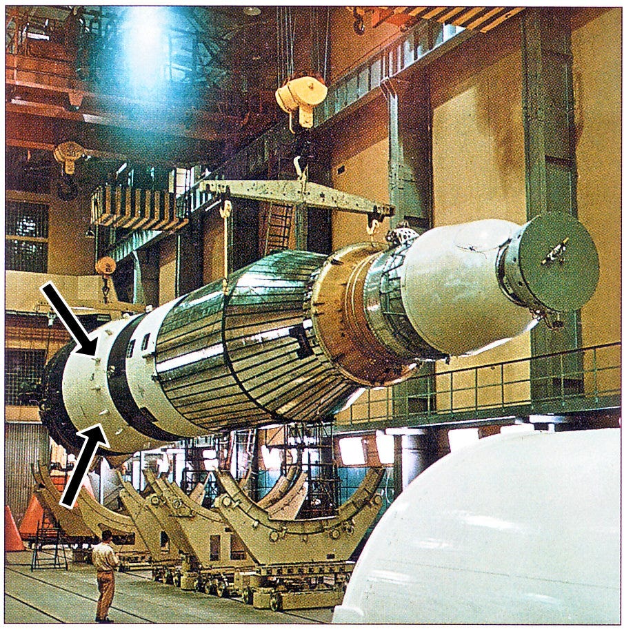
We have photo reference for the section of the N1-L3 that flies to the Moon, clearly showing a ring of structures like stubby fins. Speculation has been rife for years on these, with one popular idea being that they were a ring of antennae.
Here they are in a photo:
And here in a reference render by me:
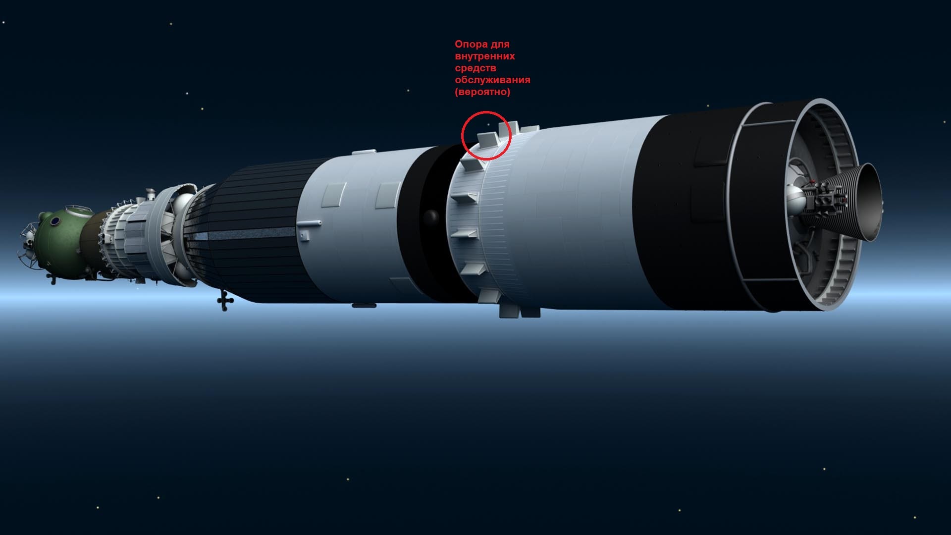
Vladimir Antipov, (Who contributed to the first edition N1 book, based on his experiences working at Baikonur shortly after the N1 program, and setting up the N1 Museum there), has stated that:
“There is a 1-metre gap between the nose fairing and the inner shell so that the SC service personnel can enter the fairing through the tower and work with the booster blocks and ships in a circle in any plane. There were corresponding service platforms inside the GO”
This discussion was triggered by questions of why the inner hull (as seen in the photo above), was there. Vladimir also stated: “In addition, the inner shell transfers the thrust force of the lower stages to the upper LOK ship.”
Or, to put it another way, the inner hull is load bearing, the outer hull / L3 fairings are not.
Vladimir is NOT prone to speculation, and I trust his call on this one.
“Shams” added: Let me try to explain. Imagine the L-3 head block on the SP in a vertical position. The LOK cannot simply be placed on top of the LK, it will crush it. Therefore, the LOK rests on the shell inside which is the LK. In turn, the shell with the LK rests on the shell inside which the D block is located
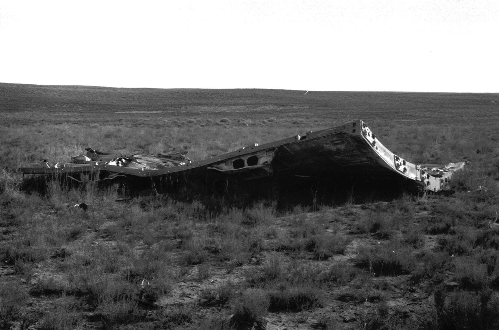
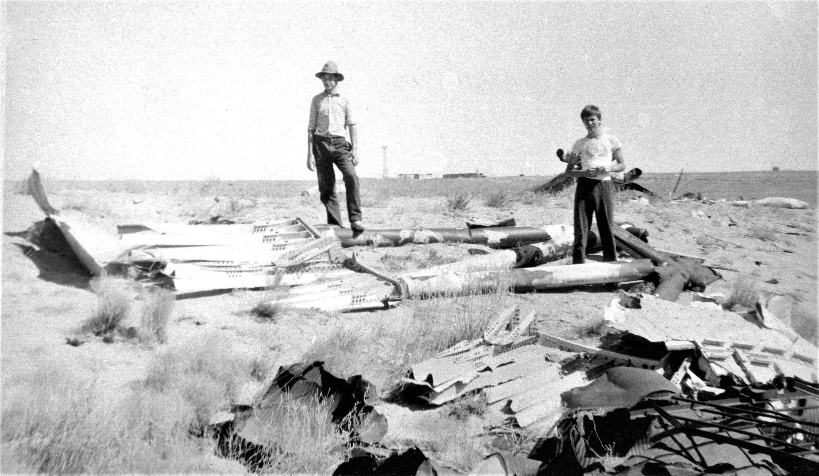
More debris photos.
All wreckage photos are copyright Vladimir Antipov - He contributed many photos from his research for the first N1 book, but not for online publication. He has now put these on the NK forums.
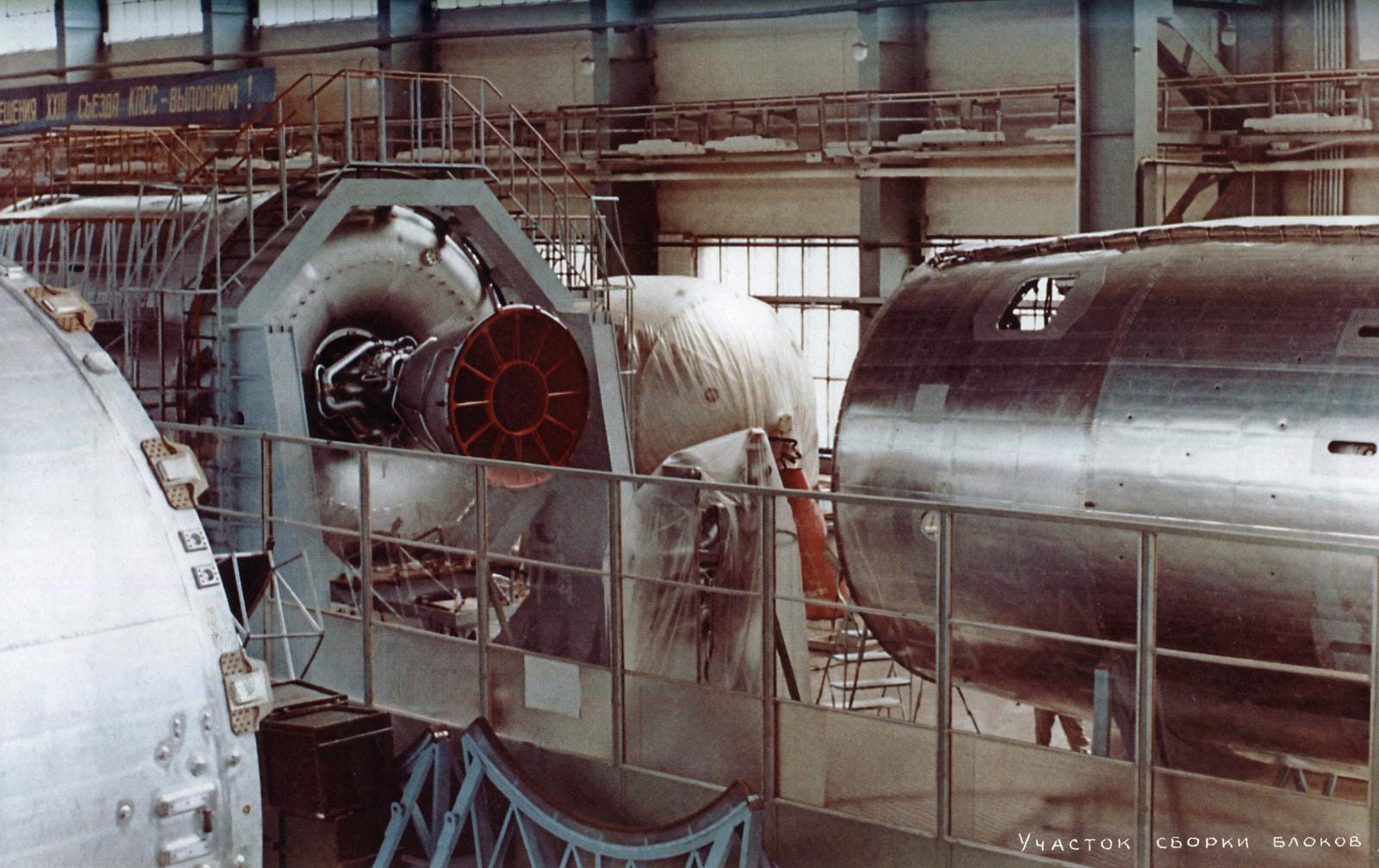
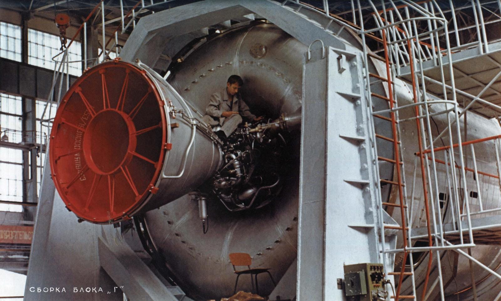
And, wrapping up this long post, two colour photos of Block G in the factory.
Follow up:
I plan on following up this post shortly, I will report back on if the context has improved, and make some 3d renders to show the how these relics fit in with the overall view of the N1.
This edition’s cool link:
https://spaceflighthistory.blogspot.com/2017/07/sei-swan-song-international-lunar.html

The American plan to use Energia for exploring the Moon.
“The one-way automated cargo landers, each rectangular in shape and capable of delivering 11 metric tons of payload to the Moon's surface, would be assembled and packed in the U.S. and shipped to Russia in C-5 Galaxy or Antonov-124/225 transport planes, then launched on Energia rockets from Baikonur Cosmodrome”
This edition’s cool image:
As we have just had international women’s day., this seems appropriate!

This edition’s 7 day download:

For a change, (and as a contrast to the techie content on the rest of this edition), I thought you might like a bundle of 20 Soviet Space Propaganda Posters. I’ve cleaned these up, and enlarged them with AI software.
Thank you, Very interesting!
Названные Вами «поршни» - это, на самом деле, пирозамки. Хвостовые отсеки соединялись с ракетными блоками 24-мя пирозамками. А после раскрытия замков на продольных стыках створки Блока Б разбрасывались пороховыми двигателями (максимальное рассогласования запуска которых, между прочим, 0,003 секунды), а Блока В — пружинными толкателями.
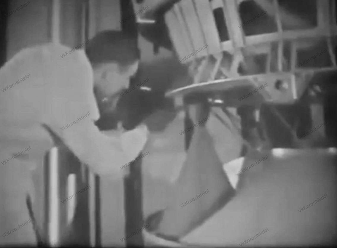
Вот тут кадры с установки двигателей и испытаний по отделению хвостовых отсеков Блока Б:
https://drive.google.com/drive/folders/1DeZkxxu1rbR6R4UkzOuEG1Es4FBfDIX0?usp=sharing