LOK Electrical Systems
Technical Information
Introduction:
This post is a bit different - I found a technical article in Russian, with lots of photographs and technical information. It may well be a bit long and deep for many, but hard information is so hard to find, I thought it worth sharing. Let me know if you would like more of this kind of thing.
The original is here:
https://vk.com/@starbase_space-energoustanovka-lunnogo-orbitalnogo-korablya
And the author retains copyright.
As usual, acronyms are a nightmare! Refer to the original if these are important to you. Phrasing is still a bit clunky, I’m reluctant to change things unless I’m sure it won’t alter the meaning.
Spacecraft Reference Photos
After polls on Social Media, it seems that many of you would like access to my reference photos of spacecraft, taken in various museums. So…
Over 300 photos, and over a gigabyte of data. Subjects covered include:
LK Lander in London
Lunokhod in London
Soyuz 7K-0K
Sputnik 3 official model
Venera Official Model and Parachute
Vostok 6 in London
Black Arrow Rocket
Blue Streak Rocket
Skylark Rocket
Launch price $8, going up to $10 on Monday. More info, Buy it here:
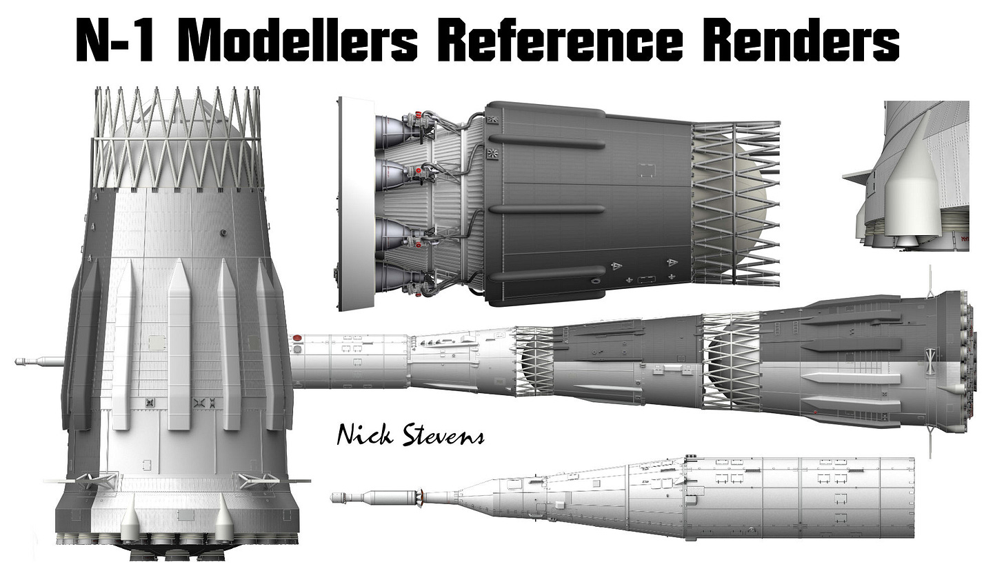
I’m also offering a 25% discount on my N1 Reference renders until Monday. SALE PRICES WILL NOT BE EXTENDED! Click on the pic!
7K-LOK Spacecraft power plant
In the Soviet Union the work on creation of space power supply on the basis of hydrogen-oxygen fuel elements was started in RSC Energia in 1967 for the lunar orbital spacecraft (LOK) of the L3 Lunar Expedition.
Creating such a power supply was a complex scientific, technological and production task that required research and problem solving in various branches of science and technology: electrochemistry, material science, electrical engineering, thermal physics, cryogenics, gas dynamics, instrument engineering, mathematical modelling and involvement of wide cooperation in various branches of the national economy.
The main problem was the development of domestic TE and ECH. All of the leading organisations in the country that had laboratory experience of fuel cell development were involved in this work on a competitive basis: All-Union Research Institute of Current Sources (VNIIT) (nowadays NPO Kvant); Kudinovsky branch of All-Union Research Institute of Electro mechanics (KF VNIIEM); Ural Electrochemical Combine (UECK); Institute of Electrochemistry of the USSR Academy of Sciences (IEL AN), Moscow Power Engineering Institute (MPEI). A number of educational and scientific institutes carried out experimental work on various types of TE.
The task to create ECG for EE of LOK in the shortest terms was set before the three first organisations according to the common technical task on a competitive basis. In order to ensure tight deadlines for development of ECH of LOK the lead developer - RSC Energia - decided to develop for three versions of ECH universal subsystems of ECH most closely related to ECH: system of storage and supply of cryogenic components (hydrogen and oxygen); ECH thermal management system with autonomous means of heat removal (radiation heat exchanger and heat exchanger-evaporator, which takes away heat due to evaporation of reaction water of ECH into space).
Within a year and a half after the start of development the first ECTs of the three organizations were built and tested at RSC Energia test benches. Wave-10" ECHG and then "Wave-20" ECHG (developed by UECC) with alkaline circulating electrolyte with "classical" scheme of heat and mass exchange turned out to be the most acceptable by all main indicators: efficiency, weight, dimensions, reliability and service life. This was facilitated by the vast experience of UEIP in creating porous media for gaseous diffusion separation of uranium, as well as the experience of the Ural Electromechanical Plant in creating the most complex electromechanical systems.
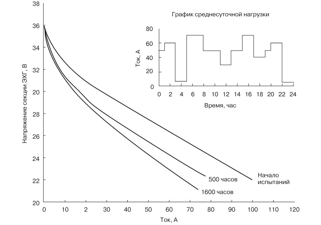
At that time, the volt-ampere characteristics of the "Wave-20" ECG sections were among the best in the world.
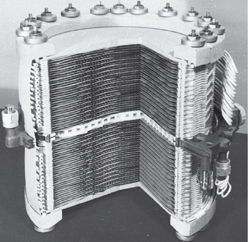
Figure 1. ECHO "Wave-20" section.
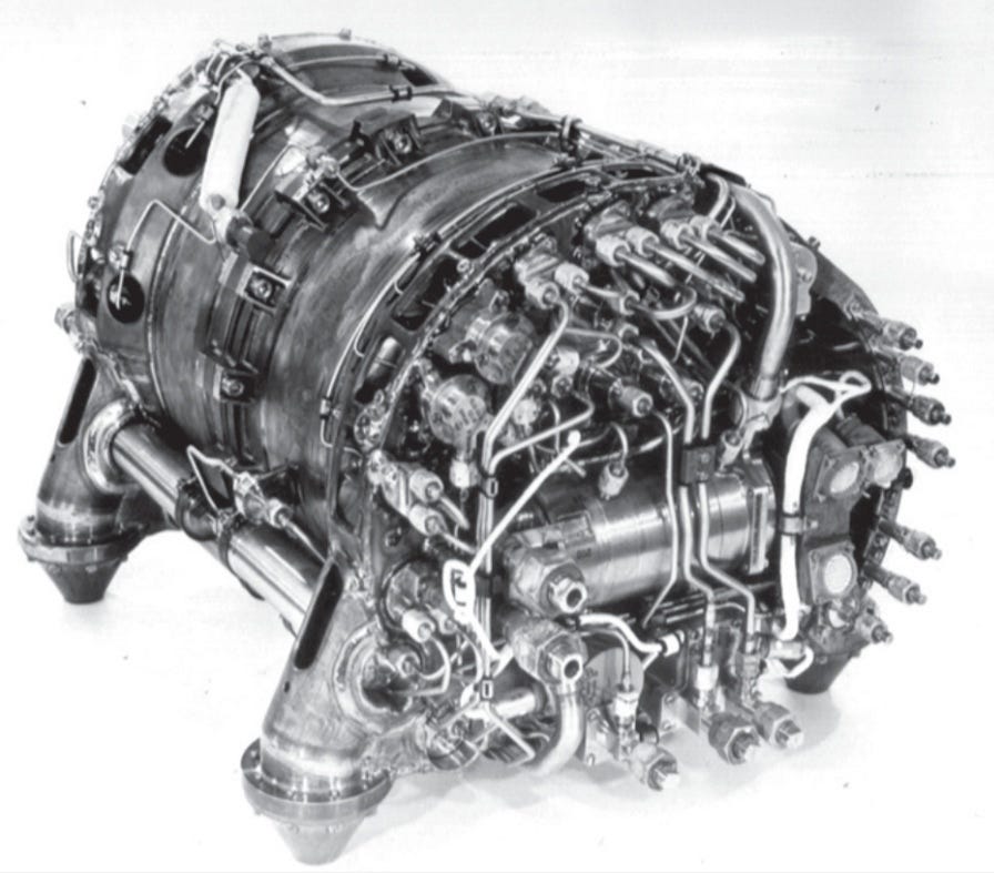
Fig. 2. Thermal power unit section of "Wave-20" ECHG.
Fig. 3. Volt-ampere-current characteristic of the "Volna-20" section and its changes during the tests.
The ECH delivery set consisted of three self-contained ECH power units, called sections, a switching, control and monitoring unit of commutator-less motors of a centrifugal pump and a vortex compressor of a steam-hydrogen mixture and an automation unit. The weight of electrolyte, coolant and water filled ECH section (taking into account a share of weights of the automation and switching units, designed for operation of three ECH sections) made 69 kg, power -1,1 kW. Since 1971 the production volume of one-kilowatt (at voltage 27 volt) sections was 45 pieces per year. In total 192 ECH sections were produced.
The second problem was the development of highly efficient storage tanks for cryogenic components, ensuring the supply of ECH with hydrogen and oxygen with specified parameters during the entire operation period without loss of components. The component storage and supply system (SCS) is one of the main systems of ECH determining its mass-size characteristics. The efficiency of hydrogen and oxygen storage has the greatest influence on the acceptability of the whole EE for a spacecraft. Table 1 presents the results of analysis of various hydrogen and oxygen storage modes from the position of minimum mass of storage system design.
Table 1. Results of Analysis of Various Hydrogen and Oxygen Storage Methods
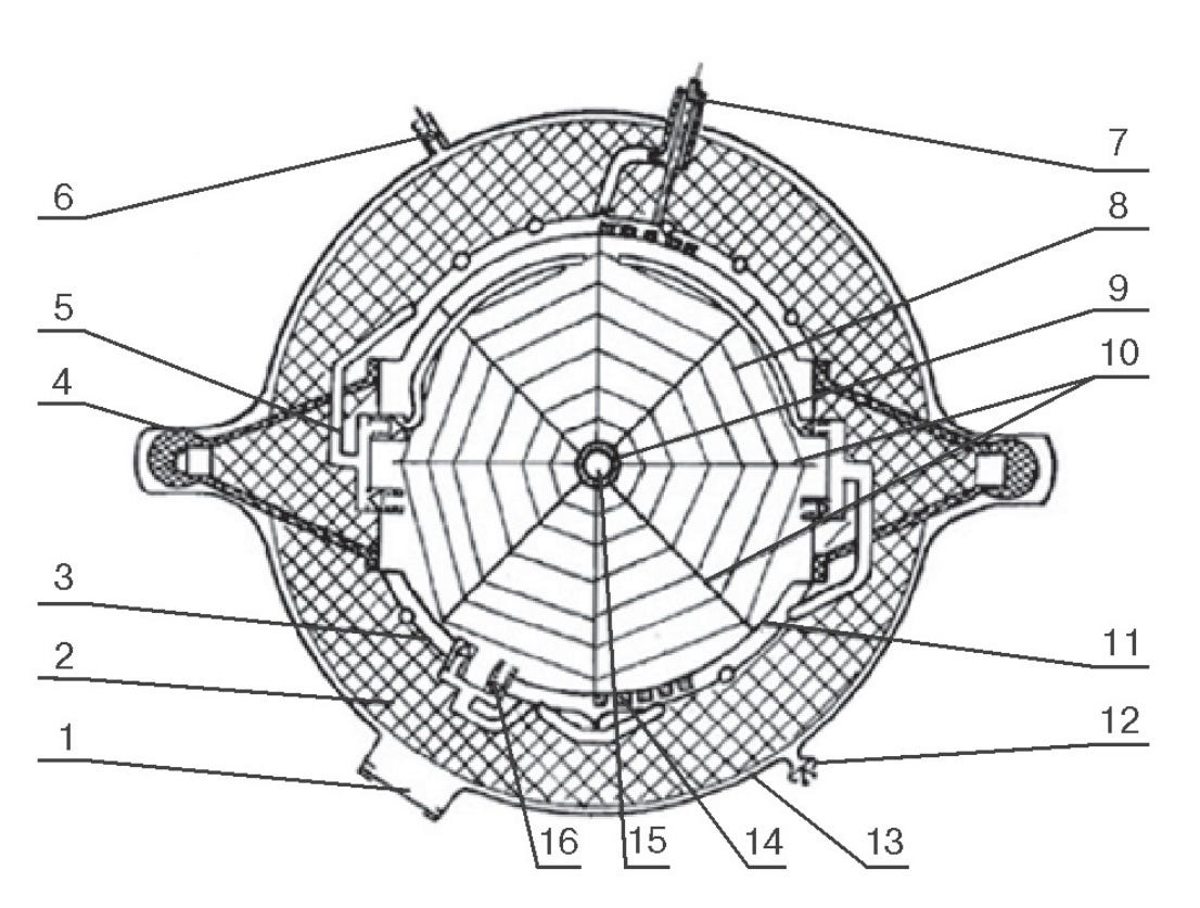
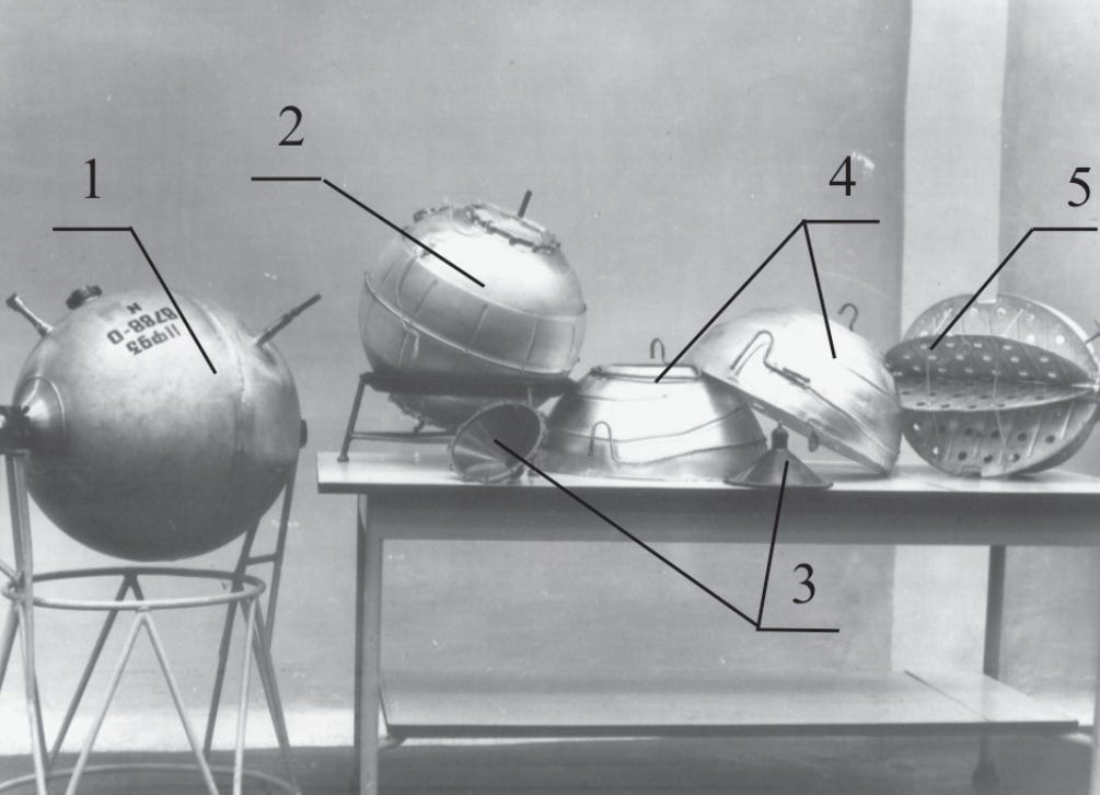
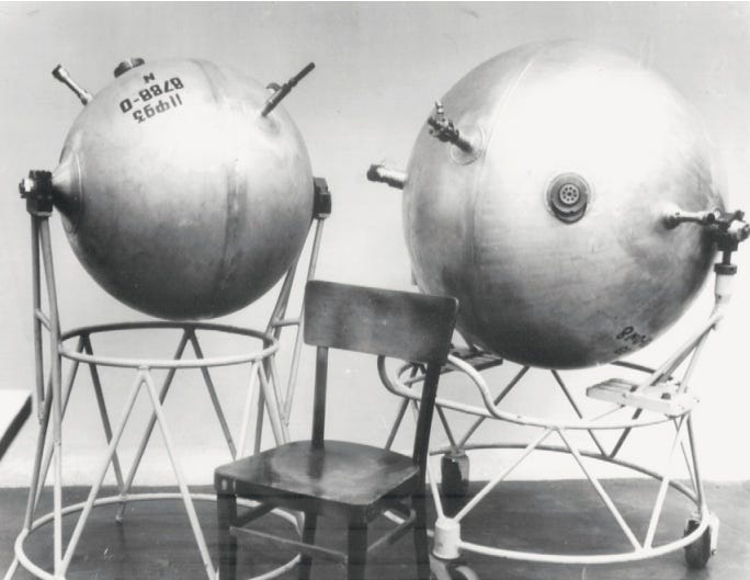
The scheme with "static", (using electric heater without forced circulation of component), pressure maintenance in cryogenic tanks with subcritical storage of oxygen (P ≤ 25 kgf/cm2 ) and supercritical storage of hydrogen (P ≥ 12 kgf/cm2) was selected by RSC Energia. Fig. 4 represents constructional diagram of oxygen cryogenic storage unit. Fig. 5 shows a cross-section of the oxygen cryogenic storage unit, and Fig. 6 shows internal capacity of oxygen cryogenic storage unit with cooled screen. Fig. 7 shows oxygen cryogenic storage unit and its components, and Figure 8 shows oxygen and hydrogen cryogenic storage units. The hydrogen and oxygen cryogenic storage units were designed and manufactured at RSC "Energia", and tests on cryogenic components were carried out at NIIChIMMASH.
Figure 4. Construction scheme of oxygen cryogenic storage unit:
1 - safety membrane; 2 - thermal insulation; 3 - cooled screen; 4 - support; 5 - supercharger drainage collector; 6 - vacuum valve; 7 - filling and drainage pipeline; 8 - quantity sensor wire; 9 - electric heater; 10 - thermal fins; 11 - inner containment; 12 - depressurization valve; 13 - outer containment; 14 - adsorbent; 15 - inner electro heater area; 16 - throttle valve.
Figure 5. Sectional view of the cryogenic oxygen storage unit:
1 - outer shell; 2 - inner shell; 3 - EVTI; 4 - electric heater fin; 5 - quantity sensor antenna; 6 - electric hermetic outlet from the inner tank.
Figure 6. Internal capacity of oxygen cryogenic storage unit with cooled screen: 1, 2 - left and right sections of cooled screen; 3 - flow line; 4 - adsorbent suspension to maintain vacuum in EVTI.
Figure 7. Cryogenic oxygen storage unit and its components:
1 - oxygen cryogenic storage unit; 2 - inner shell with a grid for fixing the adsorbent; 3 - glass-textolite supports (thermal bridges); 4 - sections of the cooled screen; 5 - electric heater housing with ribs, on which the antenna of the quantity sensor is fixed.
Figure 8. Oxygen and hydrogen cryogenic storage units.
The third problem was creation of specialized shops and areas for fabrication and assembly: fuel cells, fuel cell batteries, structural elements and ECH as a whole at UEIP; cryostats for hydrogen and oxygen storage, hydrogen and oxygen cryogenic and "warm" fittings, heat exchangers, automation and electric power switching devices, structural elements and ECH as a whole at RSC Energia.
The fourth problem was the creation of specialised test benches: at UEIP - pneumatic and strength tests of ECH units and aggregates and generator as a whole; including testing its operation on gaseous hydrogen and oxygen; at RSC Energia - pneumo-electric tests of cryostats for hydrogen and oxygen storage, ECH units and aggregates and power unit as a whole; at TSNIIMASH - strength tests of cryostats for hydrogen and oxygen storage, as well as power unit as a whole; at NIICHIMMASH - cryogenic tests of cryostats for hydrogen and oxygen storage as well as power unit as a whole during operation under electrical load.
The fifth problem was the creation of ground infrastructure, providing operation of power unit: technology development and mastering of production of liquid hydrogen and oxygen of special purity (Í2 – 99.9999%; Î2 – 99.999%), including instrumentation and methods of its purity measuring (RSC "Applied Chemistry"); development and manufacture of means for transportation, storage and filling of cryogenic hydrogen and oxygen of special purity ("Uralkriomash", NPO "Cryogenmash").
The LOK power plant (Fig. 9) is intended for supplying onboard equipment with electric power, the ship's crew with oxygen for breathing and water for drinking and domestic needs. In addition, water can be used in the evaporation units of the ship's thermal management system. The power plant consists of the following functional systems: the ECH, the working body storage and supply system, the thermal management system, the integrated control, monitoring and electric power switching system.
Figure 9. Structure diagram of the Lunar orbiter's ECU:
ACS - components storage and supply system; FDA - filling and draining valve; BHC - oxygen storage unit; BHB - hydrogen storage unit; BA ACS - ACS automation unit; GGTG - gas-liquid heat exchanger - gasifier; ECH - electrochemical generator; BA ECH - ECH automation unit; RB - power unit; BC ECH - ECH commutation unit; RSC - power commutation unit; SOTR - thermal mode support system; BA SOTR - SOTR automation unit; ATO SOTR - SOTR units and heat exchangers; RTO - radiation heat exchanger; PO - instrumental compartment; EA - energy compartment.
(Note! This one is pretty much 100% acronyms, see the link to the original)
ECH consists of three power units (three ECH sections), auxiliary power switching unit EB and an ECH automation unit. ATS consists of two hydrogen cryogenic storage units, two oxygen cryogenic storage units, filling and drainage fittings, a gas-liquid heat exchanger, an evaporator and a component supply unit to the ECH, as well as an ATS automation unit.
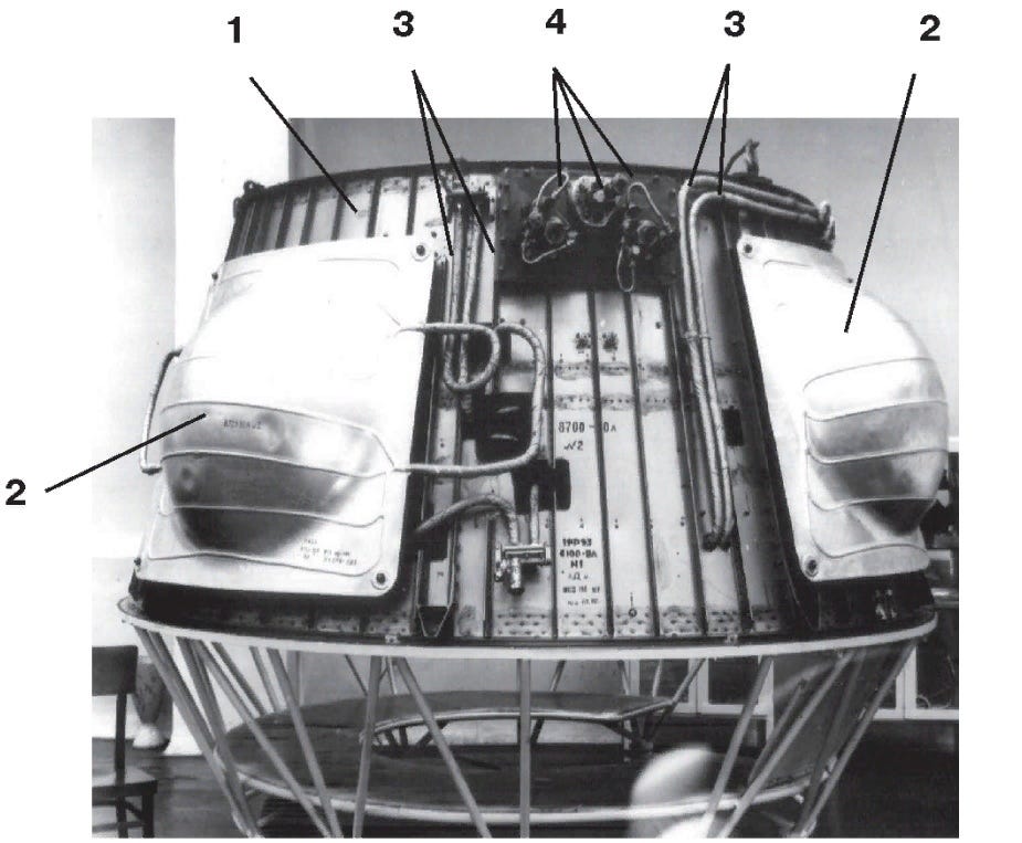
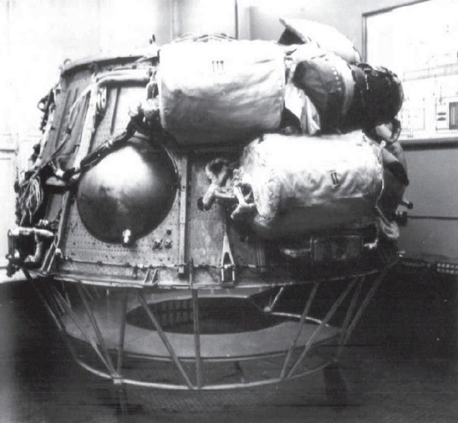
The PSC consists of units and heat-exchange devices, which provide the ECH heat removal to the PSC hydraulic circuit and the radiation heat exchanger, which provides the heat removal to the space, as well as the PSC automation unit. The integrated system of control, monitoring and electric power switching consists of the power switching unit (PSC), which provides switching of electric power supply of the ECH power units to the common buses of the power unit, as well as of the automation units built into each subsystem of the power unit. The power plant is located in two compartments of the LOK: the conically shaped transition section of the LOK, also called the power section (PS), accommodates the main power units: the ECT, cryogenic hydrogen and oxygen storage units, units of the thermal management system, etc.; the sealed instrument compartment (DC) of the LOK accommodates instruments of automatic control, monitoring and electric power switching. Figures 10-12 show the location of the ECH, hydrogen and oxygen cryogenic storage units and other components of the power plant in the transition section of the LOK.
Fig. 10. Location of power units on the LOK transition compartment:
1 - compartment hull; 2 - hydrogen cryogenic storage units under the radiation heat exchanger panels; 3 - coolant pipelines of the SOTR; 4 - fuelling-draining and controlling hydrogen pads.
Fig. 11. Placement of ECHG and cryogenic oxygen storage unit on the LOK transition bay. On the upper right EHG the thermal insulation has been partially removed.
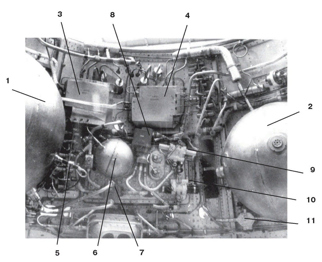
Fig.12. Internal layout of the power units on the LOK transition section:
1 - hydrogen cryogenic storage unit; 2 - oxygen cryogenic storage unit; 3, 4 - hydrogen and oxygen filling and drainage units; 5 - pressure alarm panel; 6 - SOTR volume compartment; 7 - liquid-liquid heat exchanger; 8 - liquid flow rate controller; 9, 10 - SOTR hydraulic units; 11 - temperature sensor unit.
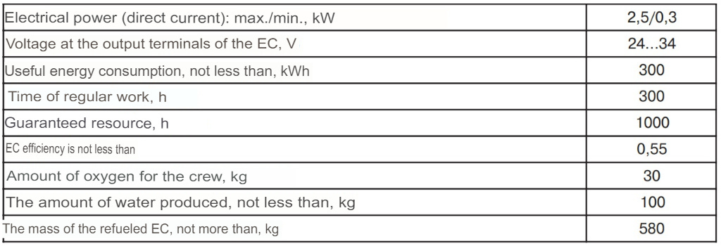
The LOK ES was created following the U.S. Apollo spacecraft ES. Since both spacecraft were designed to deliver astronauts to near-lunar orbit with their subsequent descent to the Moon and return to the LOK (Apollo) with further return in the LOK (Apollo) to Earth, their structure turned out to be quite similar. Each EV has three ECHs, two hydrogen and two oxygen cryogenic capacities, approximately the same power and energy capacity, etc. (see Table 1). The main difference is the type of ECG. In "Apollo" ESP with middle-temperature alkaline TE (Trab=200...260°С) is used, and in LOK ESP with low-temperature alkaline TE (Trab=94...100°С). In the first case some higher efficiency, but because of the design features in two times higher specific weight (125 kg/kW instead of 65 kg/kW) and because of more intensive corrosion processes in electrodes, connected with higher operating temperature, the guaranteed service life is halved (500 hours instead of 1000 hours).
Table 2. Main characteristics of the LOK power plant.
By 1970 the design, fabrication and initial development of all components and assemblies of the ESP including ECH, were finished and complex tests in NIICHIMMASH were started.
By the middle of 1972 the power plant had gone through a full cycle of ground-based experimental development, its prototype had undergone pneumoelectric tests as a part of LOK at the assembly and testing facility at the Baikonur Cosmodrome, and then as part of the N1-L3 rocket-space complex it was taken up for launch.
On November 23, 1972, the fourth (final) launch of N1-L3 complex took place, where the power unit with ECH was used for the first time. This unit provided, without any faults, power supply to all the LOK systems with the following parameters: in the prelaunch phase ~ 10 minutes, in the take-off phase up to the explosion of the first stage (block A) ~ 110 seconds, in the free fall phase up to the ground impact ~ 200 seconds.
The LOK power installation, created in a very short time, was the first power installation with ECT in the Soviet Union. It paved the way for the development of such power plants not only for space purposes but also for wide application in ground and underwater services, as well as in transport.
List of references:
[1] H. Mac Brayar. Fuel Cell Systems for Manned Spacecraft. // Proc. conf. Electrochem. Power Sources Systems for Space Applications-Paris: D.47 dec.1967, p.21-34.
[2] V.P. Mishin, M.V. Melnikov, V.S. Ovchinnikov, E.I. Grigorov, S.A. Khudyakov, et al. Power Supply System for the Lunar Orbiter LOK-LZ on the Basis of Electrochemical Generators with Hydrogen-Oxygen Fuel Cells. // Preliminary Design - Korolev: RSC Energia, 1969, P4341-505, 209p.
[3] Ferguson P.L. Apollo Fuel Cell Power Systems // 23rd Annual Power Sources Conf. 1969, p. 11-13.
[4] Mishin V.P., Melnikov M.V., Ovchinnikov V.S., Grigorov E.I., Khudyakov S.A. et al. Results of Flight and Design Tests of Power Supply System for Lunar orbital spacecraft LOK-LZ No.6A during launching of launch vehicle H1 No.7 // Technical Report - Korolev: RSC Energia, 1973, P9553, 27p.
This Editions Cool Image!
Lunar L1 control panel, with translated captions!
This editions cool link:
I’m going to plug the chap who wrote the original Russian article on the LOK Power systems again. He deserves it!
https://vk.com/@starbase_space-energoustanovka-lunnogo-orbitalnogo-korablya
That’s all folks!







I’d love more of this sort of stuff. So much knowledge is locked away from the anglophone world in places like VK posts. You can’t just Google and stumble into them if you don’t speak Russian. So I find this unique and exciting.
Hi Nick, for some reaon your link to the space pictures for sale only leads to a picture, no option to buy. Tried in Edge and Firefox