Just as I was finishing up the previous post, more information arrived. The article was already close to the recommended maximum length, so I saved it for a second instalment.
If you didn’t read Part 1 yet, it would make sense to read that first, you will find it here: 1987 Nuclear Mars Plans, Part 1
Rejected Options
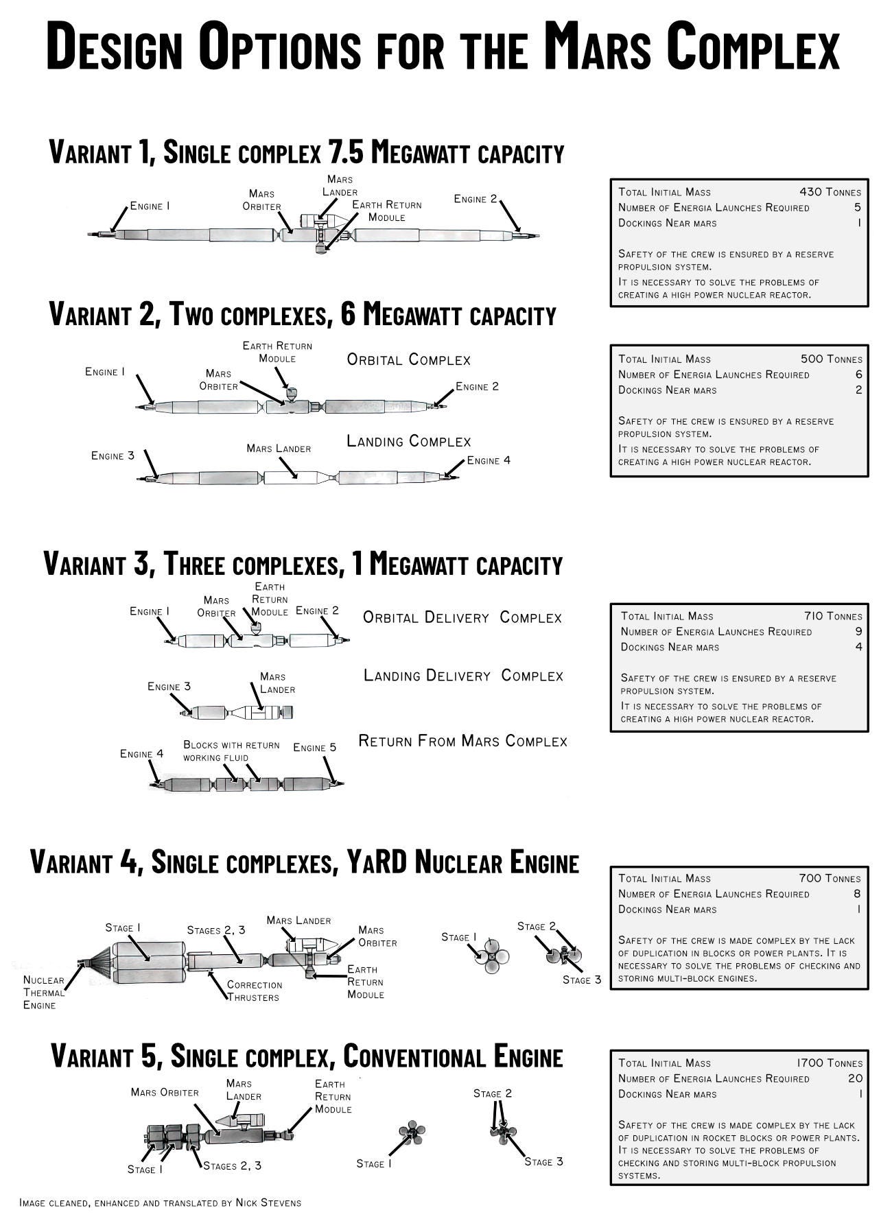
Five major configurations of the Mars flight hardware were considered, before recommending the first option as the way forward. These were:
1 large nuclear electric complex
2 smaller nuclear electric complexes
3 smaller nuclear electric complexes
A powerful nuclear thermal engine
A chemically fuelled conventional vehicle
These are summarised in the following chart:
As usual you can see a larger version of an image by clicking on it.
Variant 1
This was well covered in the previous post.
Variant 2 - Two vehicles
This is broadly similar to the first variant, but 2 separate craft are used. The engine power is a bit lower, but it requires an extra launch, 6 launches instead of 5. The 2 major elements now need to dock at Mars.
Variant 3 - Three Vehicles
The energy requirement is a LOT lower now, but there are 4 dockings near Mars, (Ouch!), and the number of launches required has increased to 9. This looks dangerously complex.
Variant 4 - YaRD type nuclear engine
This uses a high-powered nuclear engine, instead of the low powered, but highly efficient nuclear electric system. As noted in the diagram, a lack of redundancy in the power/engines makes this a much riskier option. I’m guessing that developing a powerful, durable engine of a completely new type would be seriously challenging.
The weight is high, particularly when you consider how much larger the 1st variant is. This emphasises how light variant one is, with the long tubular sections being light, hollow radiators.
Variant 5 - Conventional Propulsion
This is, I suspect, included for completeness. A whopping 20 launches to get the monstrous 1700 tonnes into orbit and assembled. Very poor redundancy, and a huge assembly job in Earth orbit.
The designers chose option 1 as the only version worth taking forward.
We have video!
There’s video of the project! It’s an animation showing various mission stages. It’s clearly had the commentary converted to English by software, which leads to some strangeness. But it’s still useful in clarifying elements that don’t show well in side-on diagrams.
Here are some highlights from the commentary that I found informative:
The fuel, or rather the working fluid, is the molten metal lithium, and the last launches are two nuclear electric propulsion systems.
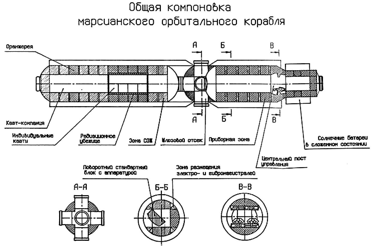
The astronauts will live and work in the orbital module of the spacecraft for the multi-year flight. Here the crew has control posts, cabins, and a greenhouse at their disposal.
The equipment installed along the ports of the orbital module will provide additional protection from cosmic rays.
After assembly, the propulsion systems extend, increasing the area of radiators that emit excess reactor heat.
The engine blocks will work simultaneously, but either one of them can provide the crews return to Earth at any stage of the flight.
On that last point, I’m still not clear how one engine mounted at one end of a long craft and pointing sideways won’t just spin the ship around.
We have a Russian Language PDF Book!
There’s a PDF book covering the proposed mission using variant 1. (Link is at the end of the article). Computer translation seems to struggle even more than usual, but here are some highlights I’m confident of.
The key elements for the crew, (The orbiter, Lander, and Earth return vehicle), were assumed to be the same in all variants.
Energia was assumed as the launch vehicle, but it was noted that using Vulkan would make things a lot easier.
The second variant adds complexity with the docking near Mars, but it has the benefit of allowing more weight to be sent down to the Martian surface.
The 4th variant did NOT consider a Venus flyby, as it would be less effective in modifying the trajectory, (I think due to higher speed of this variant?)
Crew Safety
These notes are particularly interesting, a high level of crew safety is planned:
In case of failure of either engine block at any part of the flight, the other one must ensure the task of returning the Martian orbiter to Earth, including the undocking of the Martian landing vehicle, even if the failure occurred before entering the working orbit near Mars.
These considerations largely determine the overall layout of the Martian Expeditionary Complex.
The placement of the Martian landing vehicle is chosen so that its undocking does not compromise the structural integrity of the rest of the complex. Therefore, the tandem arrangement of the orbiter and lander is unacceptable, as it does not ensure the return of the complex to Earth in case of failure of one engine block with the separation of the Martian landing vehicle.
This approach extended to the orbital module too:
Sectionalisation of compartments to ensure safety
Cabins for each crew member, common saloon, recreation and work areas.
To ensure the specified radiation safety it is envisaged to maximise the shielding property of the ship's instrument areas.
To ensure repair and preventive maintenance, all main equipment is located inside the shelter, if possible.
to ensure, if necessary, access to the inside of the shell for repair in case of depressurisation.
Folding solar panels have 2 purposes, to provide power before the reactors are turned on, and to provide emergency power.
Radio systems will provide:
Telephone and video communication between the Earth and the Martian Expeditionary Complex during all stages of the flight
Receiving from the Earth onboard the code information of systems control:
Transmission of telemetry information from the board to Earth on the state of systems and medical parameters of members
Ensuring radio control of the trajectory of the complex at all flight stages to ensure the necessary trajectory correction from the Earth;
Provision of internal communication between compartments, as well as between cosmonauts in spacesuits: provision of telephone communication
Exchange of code information between the lander and the orbiter
Receipt by the orbiter of telemetry information from the lander on the state of systems and health of crew members
Retransmission of telemetric information and medical parameters of the landing crew members to the Earth.
To fulfil the set tasks, the orbiter has the following facilities:
A radio system in the centimetre and decimetre bands, designed for communication between the complex and the Earth, operating through directional antennae and antenna arrays:
A radio system in the decimetre and centimetre bands for all types of communication between the lander and the orbiter at the site.
A radio system in the metre band for communication between the spacecraft and the crew members who went into space; internal voice and video communication system for use between the crew members located in different compartments of the expedition complex.
The possibility of organising laser communication between the orbiter and the Earth.
Power Systems
The ship's power supply system provides electric current supply to onboard systems during the entire flight.
The power supply sources on the ship are two independently operating nuclear reactor units with thermo-emission converters. Each of the units has two independent nuclear reactors including several reactor modules.
Electricity from the reactors is supplied to the Martian orbiter at a voltage of 120V.
The power system provides for conversion of this voltage, resulting in three power grids on board.
A 120-volt DC network (for high-power DC consumers)
AC network 120 volts (for powerful AC consumers)
DC 27.3 (for powering electronics and other consumers of relatively low power)
Space Suits
4 spacesuits arranged in pairs in each compartment
Spacewalk preparation equipment
Equipment for refuelling and checking spacesuits
Means for autonomous movement in open space of astronauts in spacesuits.
Support my work:
The work is specialist, and time consuming - if you’d like to support me, then please take a look at my Gumroad store:
https://starbase1.gumroad.com
Here you will find many cool things!
Dump of RGANTD Archive, for the source information: https://starbase1.gumroad.com/l/RGANTD
My N1 reference images, which have received 21 straight 5* ratings : https://starbase1.gumroad.com/l/N1-Reference
Spacecraft Modellers Reference Photos: https://starbase1.gumroad.com/l/CraftReference
This Edition’s Cool Image:
I only had a small low quality version of this, so I used AI enlargement.


